
High/low frequency signal quality evaluations of ECG lead signals

a high/low frequency signal and lead signal technology, applied in the field of high/low frequency signal quality evaluation of ecg lead signal, can solve the problems of high number, inability to interpret ecg at all, and inaccurate interpretation of ecg recordings

Pending Publication Date: 2018-08-30
KONINKLJIJKE PHILIPS NV
View PDF3 Cites 1 Cited by
  • Summary
  • Abstract
  • Description
  • Claims
  • Application Information

AI Technical Summary

Benefits of technology

The present invention provides a monitoring device for electrocardiograms that can evaluate and display high-frequency and low-frequency noise levels in real-time. This allows for the continuous monitoring of a patient's electrocardiogram and the identification of specific patterns of noise that may indicate potential health risks. The monitoring device includes an electrocardiograph and an electrocardiogram quality controller that can separate and evaluate the noise levels of individual ECG leads. The invention also includes various application modules for executing specific functions of the controller. Overall, the invention improves the accuracy and reliability of electrocardiogram monitoring and analysis.

Problems solved by technology

More particularly, various sources of noise induced on an ECG recording may mask diagnostic features of the ECG, which may result in an inaccurate interpretation of the ECG recordings and resulting diagnosis by a monitoring device and / or operator of the monitoring device.
In an extreme case, a high level of noise on the ECG recording makes it impossible to interpret the ECG at all.
Clearly, a low-quality ECG may cause a high number of false alarms generated by monitoring devices, particularly in critical care units (CCU) and intensive care units (ICU), which in turn may cause alarm in medical personnel.

Method used


Image

  • High/low frequency signal quality evaluations of ECG lead signals
  • High/low frequency signal quality evaluations of ECG lead signals
  • High/low frequency signal quality evaluations of ECG lead signals

Examples


Embodiment Construction

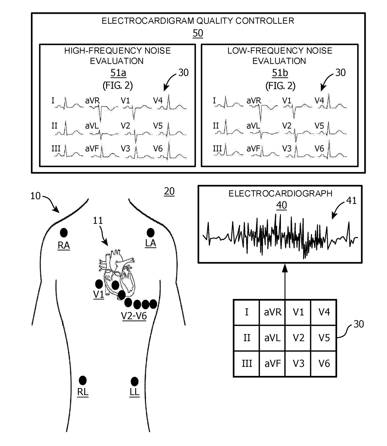
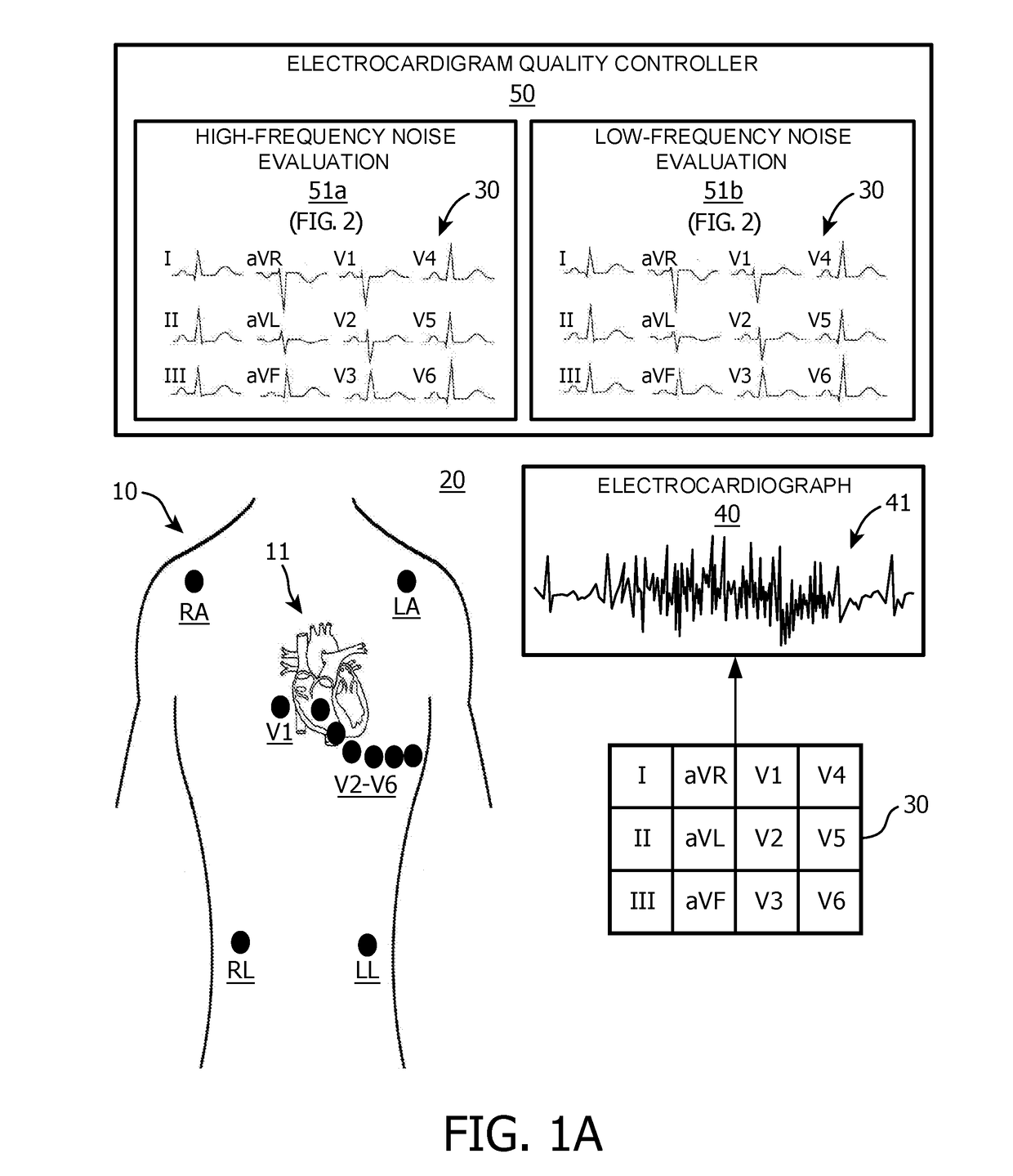
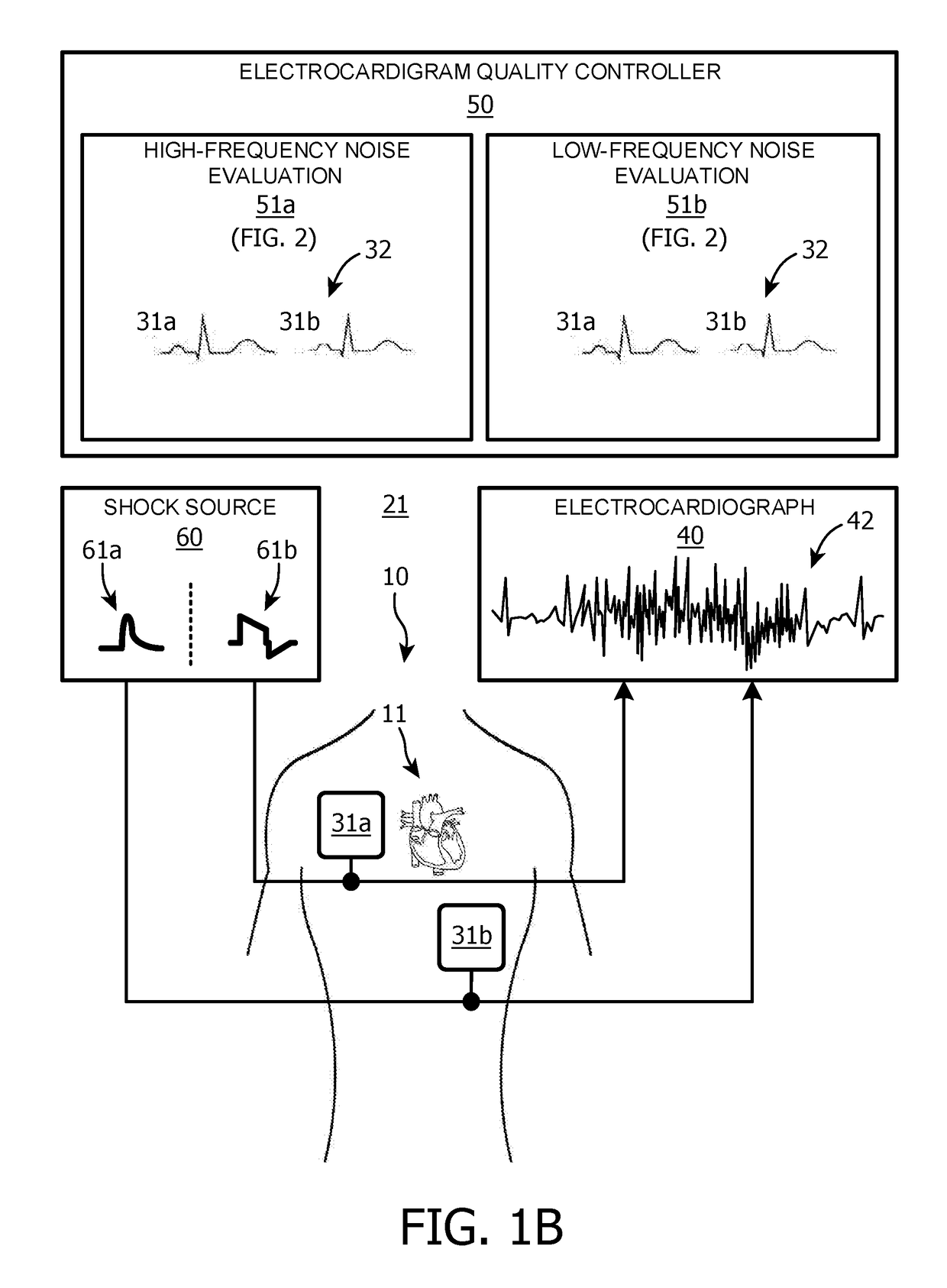
[0021]To facilitate an understanding of the present disclosure, the following description of FIGS. 1A and 1B, teaches basic inventive principles of evaluating and visually displaying a high-frequency noise level (e.g., muscle artifact and electrode motion artifact) and a low-frequency noise level (e.g., baseline wander) within electrocardiogram segments of each ECG lead in an ECG recording during a continuous ECG monitoring of a patient. From this description, those having ordinary skill in the art will appreciate how to apply the inventive principles of the present disclosure to a variety of monitoring devices displaying segments of a single lead or multi-lead continuous physiological waveform, which is often disturbed by noise or artifact that limits the interpretation and analysis of the physiological waveform, whereby the inventions of the present disclosure provides an evaluation and display of a level of noise from different sources in each individual lead.

[0022]Referring to F...


PUM


Abstract

A monitoring device (e.g., a ECG monitor or a Holter monitor) employing an electrocardiograph (40), and an ECG quality controller (50). In operation, the electrocardiograph (40) derives an electrocardiogram from one or more ECG leads (30) upon a connection of the electrocardiograph (40) to the ECG lead(s) 30 (e.g., electrode based or pad / paddle based). In response to the connection of the electrocardiograph (40) to the ECG lead(s) (30), the ECG quality controller (50) controls separate evaluations of a high-frequency noise level (e.g., a degree of muscle artifact and / or a degree of electrode motion artifact within the electrocardiogram) and a low-frequency noise level (e.g., a degree of baseline wander by the electrocardiogram) of an individual ECG lead (30) on an electrocardiogram segmentation basis (e.g., a continual ECG recording divided into segments of a specified duration).

Description

FIELD OF THE INVENTION[0001]The present disclosure generally relates to signal quality of each electrocardiogram (“ECG”) lead in an ECG recording during continuous ECG monitoring of a patient. The present disclosure more particularly relates an evaluation and visually display of high-frequency and low-frequency noise levels within electrocardiogram segments of each ECG lead in an ECG recording during continuous ECG monitoring of a patient.BACKGROUND OF THE INVENTION[0002]Electrocardiography is a non-invasive procedure for recording a multi-lead electrocardiogram (“ECG”) (e.g., a standard 12-lead ECG or a non-standard EASI lead ECG) as a representation of an electrical cardiac activity of a patient conducted to vector cardiogram or other ECG lead system electrodes on the body surface of the patient. Electrocardiography is utilized in a wide variety of clinical settings ranging from physical examinations for regular checkups and emergencies to monitoring for the preparation, operative...

Claims


Application Information

Patent Timeline
IPC IPC(8): A61B5/04A61B5/044A61B5/00
CPCA61B5/04014A61B5/044A61B5/7203A61B5/7221A61B5/316A61B5/339A61B5/318
Inventor FIROOZABADI, REZAGREGG, RICHARD EARL
Owner KONINKLJIJKE PHILIPS NV
Learn More