
Liquid ejecting apparatus

a technology of liquid ejecting apparatus and liquid ejector, which is applied in the direction of other printing apparatus, duplicating/marking methods, printing, etc., can solve the problem of affecting the function of the idle discharge receiving unit, and achieve the effect of proper flushing

Active Publication Date: 2018-08-30
SEIKO EPSON CORP
View PDF3 Cites 1 Cited by
  • Summary
  • Abstract
  • Description
  • Claims
  • Application Information

AI Technical Summary

Benefits of technology

The invention provides a liquid ejecting apparatus that can flush properly when ejecting multiple liquids. The apparatus has two collection units for collecting the liquids, which allows for effective flushing even when using multiple liquids.

Problems solved by technology

In the case of the liquid ejecting apparatus, when a plurality of types of liquids whose characteristics are different from each other are ejected to the idle discharge receiving unit, the liquids chemically react with each other in the idle discharge receiving unit, and solidification, thickening, and the like of the liquids occur, so that there is a risk of damaging the function of the idle discharge receiving unit.

Method used


Image

  • Liquid ejecting apparatus
  • Liquid ejecting apparatus
  • Liquid ejecting apparatus

Examples


Embodiment Construction

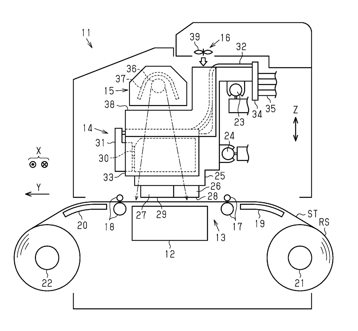
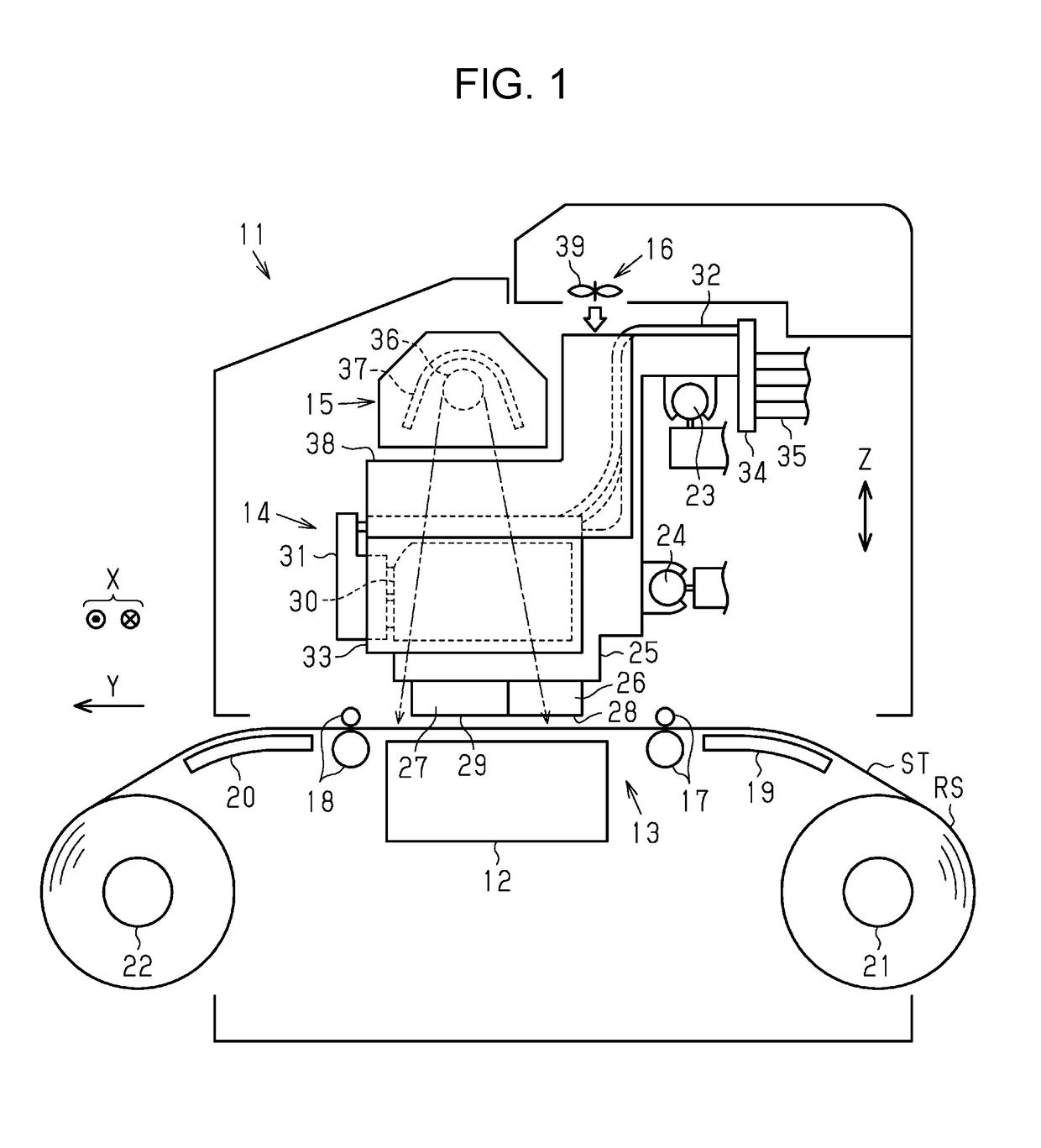
[0019]Hereinafter, an embodiment of a liquid ejecting apparatus will be described with reference to the drawings. As shown in FIG. 1, the liquid ejecting apparatus 11 includes a support table 12 that supports a medium ST and a transport unit 13 that transports the medium ST in a transport direction Y along a surface of the support table 12. The liquid ejecting apparatus 11 includes a liquid ejecting unit 14 that ejects liquid to the medium ST that is transported by the transport unit 13, and a heat generating unit 15 and an air blowing unit 16 for drying liquid attached to the medium ST.

[0020]The support table 12 is lengthily provided in a width direction X crossing a transport direction Y in a horizontal plane and supports the medium ST from below in a vertical direction Z. The transport unit 13 has transport roller pairs 17 and 18 that are arranged separately to an upstream side position and a downstream position of the support table 12 in the transport direction Y. In the transpo...


PUM


Abstract

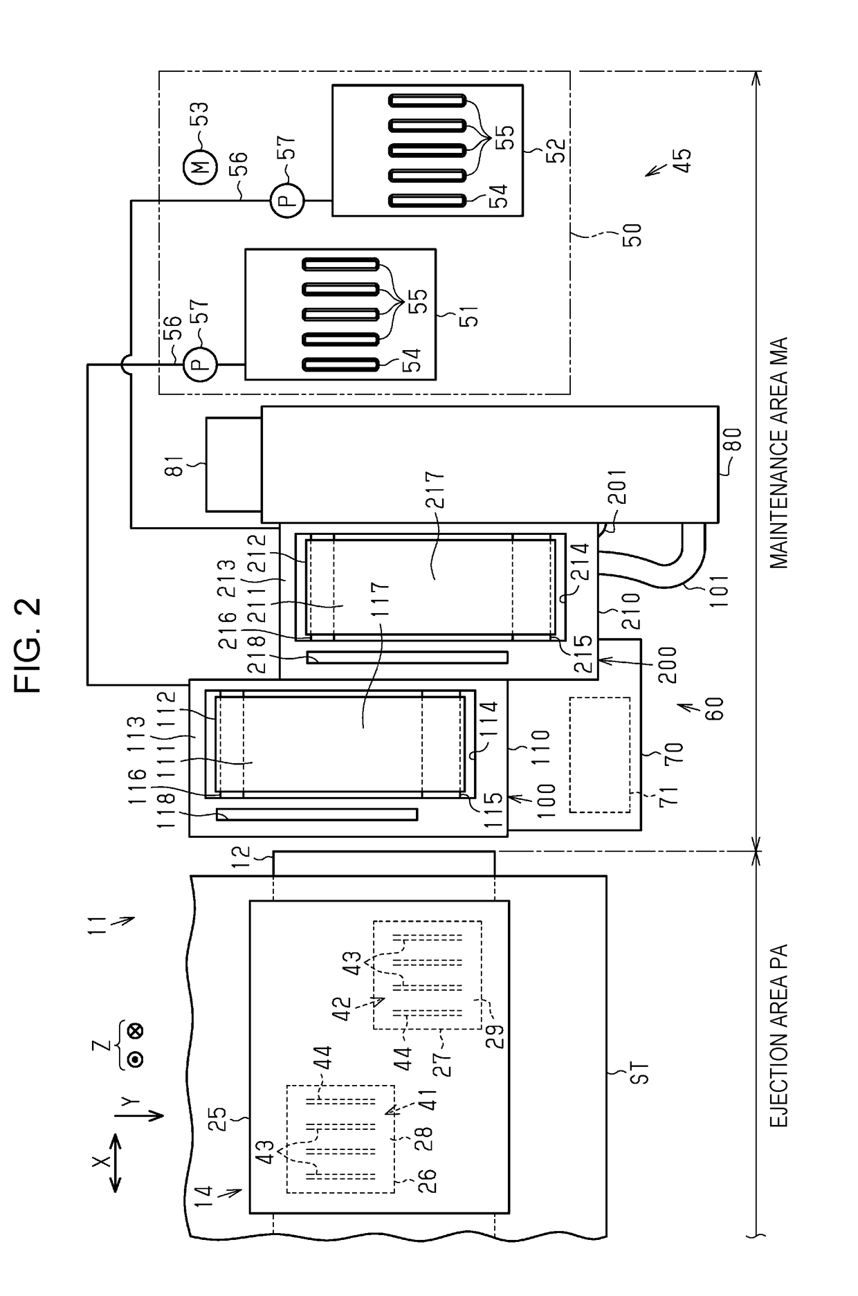
A liquid ejecting apparatus includes a liquid ejecting unit that can eject a first liquid and a second liquid to a medium, a first rotating body having a circumferential surface that can receive the first liquid ejected from the liquid ejecting unit, a first sliding contact member that can be slidably in contact with the circumferential surface of the first rotating body, a first collection unit that collects the first liquid that is collected from the circumferential surface by the first sliding contact member, a second rotating body having a circumferential surface that can receive the second liquid ejected from the liquid ejecting unit, a second sliding contact member that can be slidably in contact with the circumferential surface of the second rotating body, and a second collection unit that collects the second liquid that is collected from the circumferential surface by the second sliding contact member.

Description

BACKGROUND1. Technical Field[0001]The present invention relates to a liquid ejecting apparatus such as, for example, an ink jet type printer.2. Related Art[0002]A liquid ejecting apparatus has been known which prints an image on a medium by ejecting liquid from a head to the medium. In such a liquid ejecting apparatus, flushing may be performed where liquid that is not used for printing is ejected from the head in order to maintain or recover ejection performance of the head.[0003]As an example of a liquid ejecting apparatus, JP-A-2008-229919 describes an image forming apparatus that includes an idle discharge receiving unit that collects liquid ejected by flushing. The idle discharge receiving unit includes a rotary body on which liquid ejected from a head lands, a scraping member that scrapes the liquid attached to a circumferential surface of the rotary body, and a waste liquid container that contains the liquid scraped by the scraping member.[0004]Among liquid ejecting apparatus...

Claims


Application Information

Patent Timeline
IPC IPC(8): B41J2/165B41J2/17B41J29/17B41M7/00
CPCB41J2/16511B41J2/1707B41J2/1721B41J29/17B41M7/0018B41J2002/1742B41P2235/10B41J2/16552B41J11/0015B41J11/002B41J2002/16555B41M5/0017B41J2/16508B41J2/16517B41J2/16526B41J2/1742
Inventor SEKI, TAKANORIKIMURA, HITOTOSHIKAWAKAMI, TAKAYUKINAKANO, TATSUYA
Owner SEIKO EPSON CORP
Learn More