Self-propelled buoyant energy converter and method for deploying same

a self-propelled, energy converter technology, applied in the direction of machines/engines, renewable energy generation, greenhouse gas reduction, etc., can solve the problems of high cost, dangerous mooring and configuration of devices in this manner, and the inability of the converter to move significantly from the position of initial deploymen

Active Publication Date: 2018-08-30
LONE GULL HLDG LTD
View PDF11 Cites 16 Cited by
  • Summary
  • Abstract
  • Description
  • Claims
  • Application Information

AI Technical Summary

Benefits of technology

[0095]Elastic inter-device flexible connectors can comprise lengths of flexible, but non-stretching cables that connect a first free-floating WEC to a first float, and connect the first float to a submerged weight, and connect the submerged weight to a second float, and connect the second float to a second free-floating WEC. When the separa...

Problems solved by technology

In the prior art, buoyant wave energy converters (“converters”) are typically deployed in a “static” fashion, meaning that during deployment a converter is operatively connected to at least one mooring and/or anchor and consequently the converter is not able to move significantly from its position of initial deployment after said initial deployment.
A disadvantage of this “static” deployment method is that deploying a farm consisting of a large number of converters typica...

Method used


Image

  • Self-propelled buoyant energy converter and method for deploying same
  • Self-propelled buoyant energy converter and method for deploying same
  • Self-propelled buoyant energy converter and method for deploying same

Examples


embodiment 120

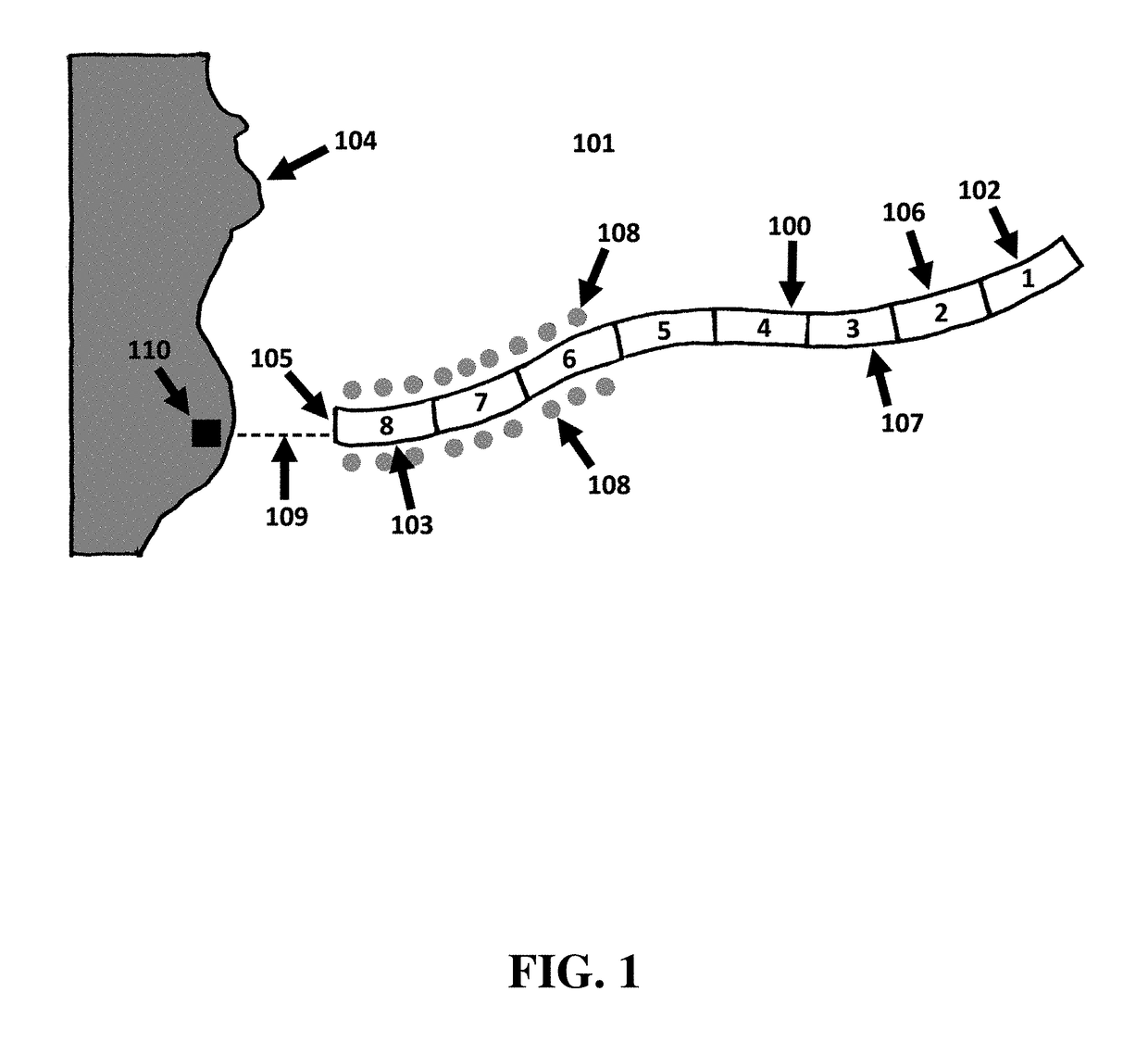
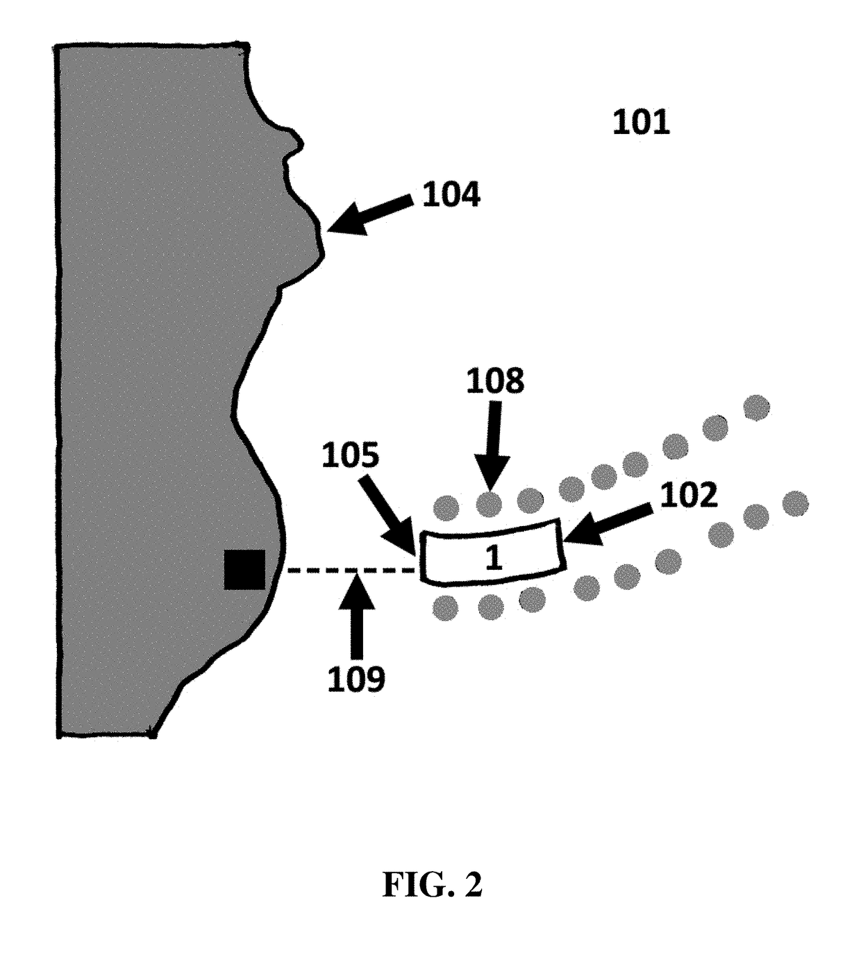
[0202]A farm embodiment 120 of the present disclosure has been extruded from a root location 121 near shore 122. Farm 120 now forms an elongate strand extending out into the ocean 124 substantially away from shoreline 122. However, farm 120 also “curves back” toward the shoreline at around 125. An anchor has been provided for the farm at 126 (this is optional). All the converters of the farm are operatively interlinked using linkages and many, if not all, of the converters are generating electricity from waves passing over the surface of the body of water on which the farm floats. This generated electricity is being transmitted, shared, combined, and / or pooled, along linkages and / or cables within the farm. Finally, the combined electricity being generated by the entire farm, and / or a portion thereof, is passing through electrical cable 127 to shore.

[0203]In this embodiment, the length of the entire farm, from 121 to 126, can be arbitrarily large, e.g. 10 km, 50 km, 100 km, or 1000 k...

embodiment 540

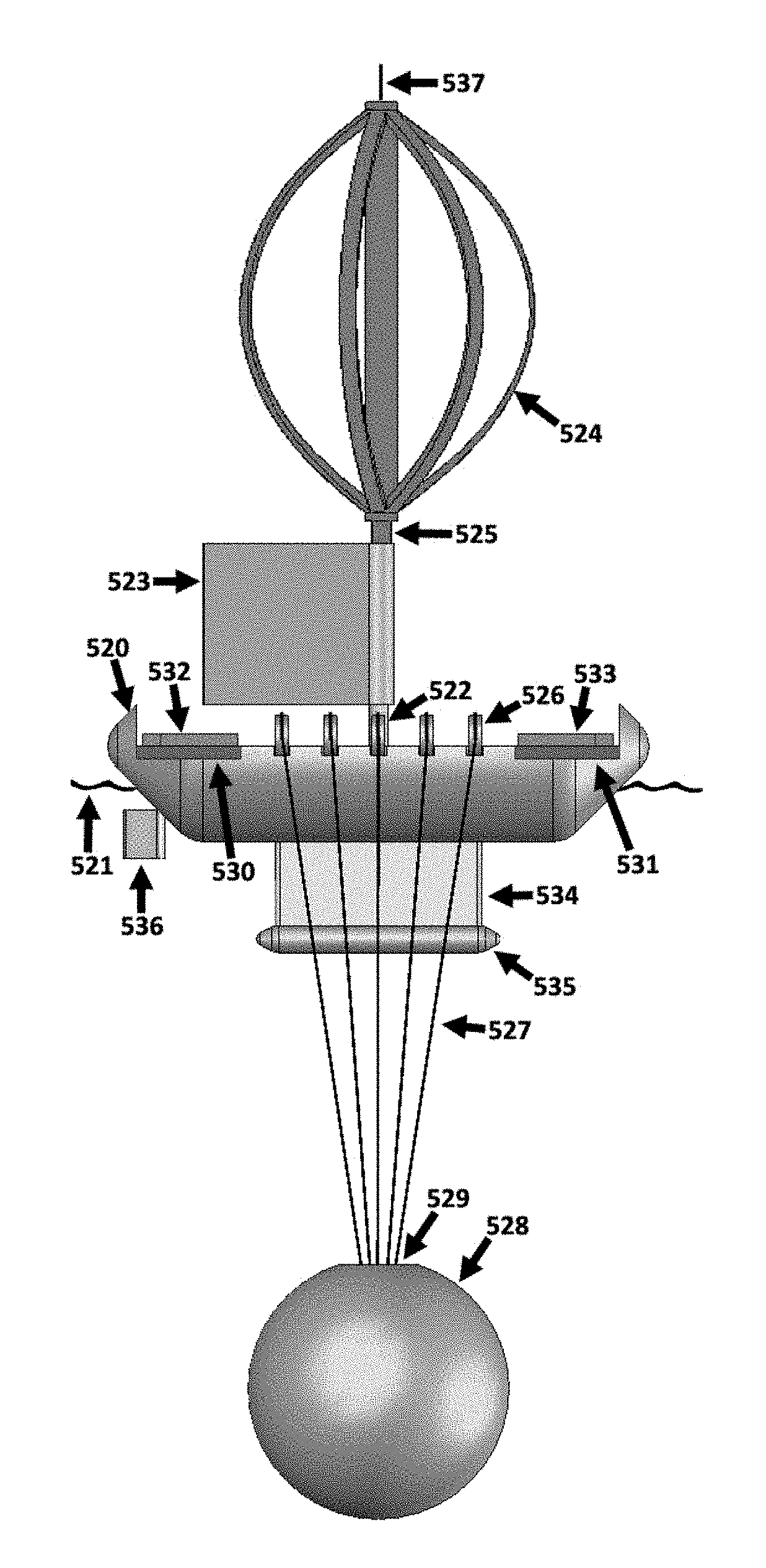
[0383]The embodiment 540 floats adjacent to an upper surface 541 of a body of water over which winds and waves pass. It 540 incorporates a Darrieus-type wind turbine 542 atop a rigid sail 543, with the turbine and the sail sharing coaxial concentric shafts. When air blows through the turbine causing it to rotate then a rotatably connected generator positioned within the buoy 540 is energized and produces electrical power.

[0384]The embodiment also extracts energy from heave of waves by means of two arrays of oscillating water columns (OWCs) embedded within opposing and parallel airfoil shaped keels 544 and 545. A rigid sail 543 rotatably connected to the top of the device provides wind-driven propulsion, and a rudder moveably connected to each keel permits the device to be steered.

[0385]Opposing pairs of airfoil-shaped keels 544 and 545 support a platform 540 at an upper portion of the device and typically above the water line 541. The keels are supported by a crossing assemblage of ...

embodiment 190

[0401]Computational modules are mounted against an interior wall of the hollow buoy 190. At least a portion of the heat generated by the computational circuits 208 is conductively communicated through the adjacent and / or common surfaces of the circuits 208 and the buoy 209, and thereafter transferred, at least in part, into the surrounding air beneath the upper portion of the embodiment 190, thereby passively cooling those circuits and avoiding the need to expend additional energy to achieve that cooling.

[0402]In an embodiment similar to the one illustrated and discussed in relation to FIGS. 36-38, the module 208 generates a chemical (e.g., hydrogen) and stores at least a portion of the generated chemical inside tanks positioned within the upper portion 190 of the device.

[0403]FIG. 46 illustrates a side perspective view of a self-propelled wind- and wave-energy converter embodiment of the current disclosure, and is representative of one of the many types of self-propelled wave-energ...


PUM


Abstract

Disclosed is a novel method, process, and system (hereinafter “method” or “process”) for deploying, stationing, and translocating buoyant wind- and wave-energy converters and/or other buoyant structures or devices, as well as farms of same. Also disclosed is a novel apparatus and/or machine comprising a farm of buoyant wave energy converters deployed by said method and/or configured to be deployed by said method.

Description

CROSS-REFERENCES TO RELATED APPLICATIONS[0001]This application claims priority from Provisional Patent Application No. 62 / 463629, filed Feb. 25, 2017; Provisional Patent Application No. 62 / 473361, filed Mar. 18, 2017; Provisional Patent Application No. 62 / 533058, filed Jul. 16, 2017; and Provisional Patent Application No. 62 / 622879, filed Jan. 27, 2018; the contents of which are incorporated herein by reference in their entireties.BACKGROUND[0002]In the prior art, buoyant wave energy converters (“converters”) are typically deployed in a “static” fashion, meaning that during deployment a converter is operatively connected to at least one mooring and / or anchor and consequently the converter is not able to move significantly from its position of initial deployment after said initial deployment. Unless a ship or boat returns to move or decommission the converter, or unless there is a catastrophic failure of the moorings, the converter will remain approximately at its designated location...

Claims


Application Information

Patent Timeline
IPC IPC(8): F03B13/18F03B13/20F03D3/00F03D3/06H02K7/075
CPCF03B13/189F03B13/1805F03B13/1875F03B13/20F03D3/005F03D3/002F03D3/065F03D3/068H02K7/075F05B2270/18F05B2240/97F05B2210/16F05B2240/93F05B2240/96F03D13/25F03D13/10F03B13/142F03B13/183F03B13/1885F05B2240/133F05B2240/212F05B2240/40F05B2240/931Y02E10/74Y02T70/5236Y02E10/727Y02E10/30F03B13/18F03D3/062
Inventor SHELDON-COULSON, GARTH ALEXANDERMOFFAT, BRIAN LEE
Owner LONE GULL HLDG LTD
Why Eureka
Try Eureka