Pinch valve for a urinary drainage system

a technology of a drainage system and a valve body, which is applied in the field of a pinch valve for a urinary drainage system, can solve the problems of reducing the lifetime and reliability of the valve body, and presenting a significant health risk to the patien

Active Publication Date: 2018-08-30
ROYAL UNITED HOSPITALS BATH NHS FOUND TRUST
View PDF14 Cites 9 Cited by
  • Summary
  • Abstract
  • Description
  • Claims
  • Application Information

AI Technical Summary

Benefits of technology

[0170]The third and fourth connectors preferably releasably connect the tube in fluid communication with the first and second connectors. Therefore, the

Problems solved by technology

As mentioned above, the formation of encrustation is a significant problem for valves for urinary drainage system

Method used


Image

  • Pinch valve for a urinary drainage system
  • Pinch valve for a urinary drainage system
  • Pinch valve for a urinary drainage system

Examples


Embodiment Construction

[0188]Embodiments of the present invention relate to pinch valves for use with a urinary drainage system comprising a urinary catheter for draining urine from a patient's urinary bladder and a urine collection bag for collecting urine drained through the urinary catheter.

[0189]A urinary drainage system including the pinch valve of the present invention can be used to control the flow of urine from a patient who requires long-term catheterisation to improve the patient's quality of life.

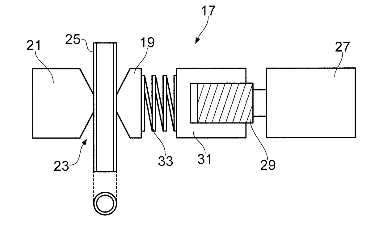
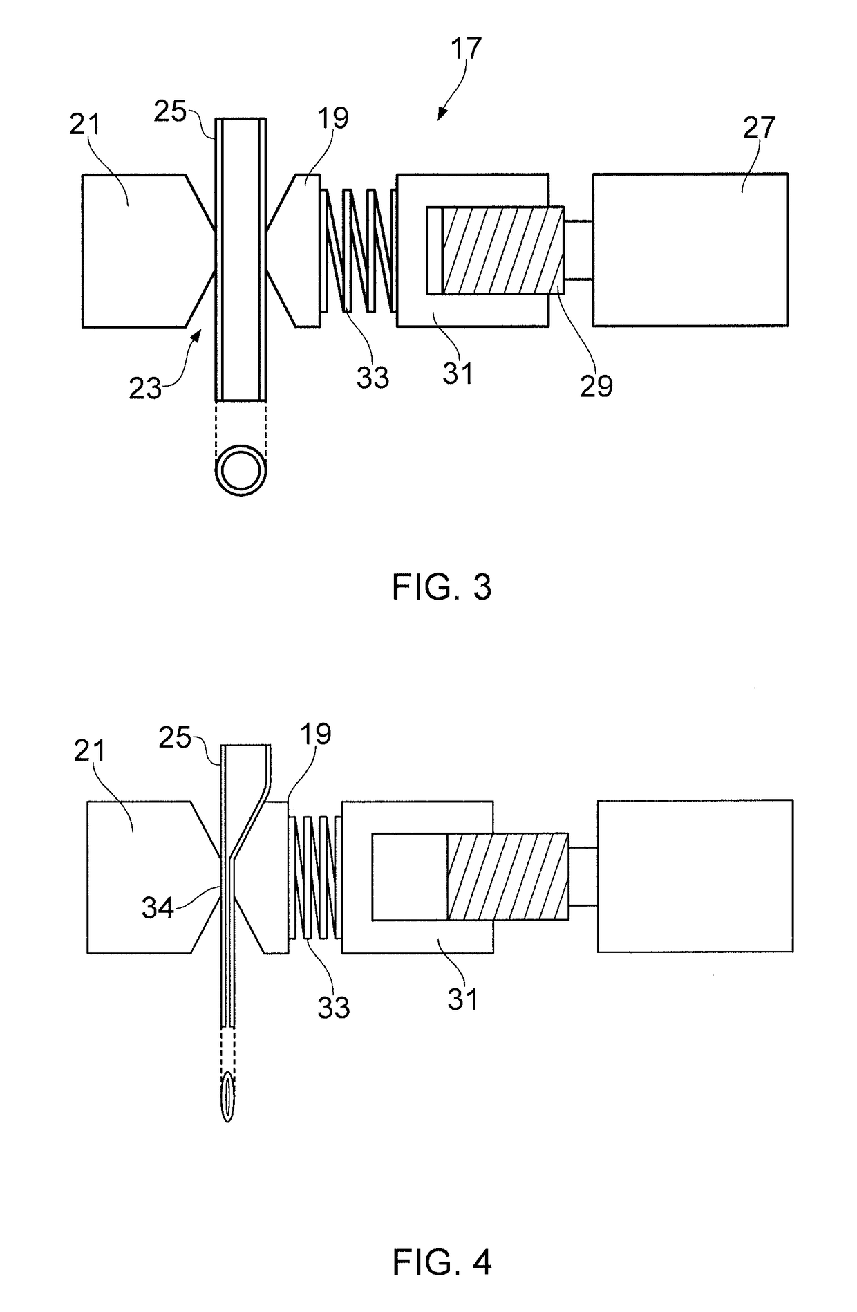
[0190]FIG. 3 is a schematic illustration of the internal valve mechanism of a pinch valve according to an embodiment of the present invention.

[0191]As shown in FIG. 3, the pinch valve 17 comprises a first pinch part 19 and a second pinch part 21 separated by a tube receiving region 23 for receiving a tube 25. he first pinch part 19 and second pinch part 21 are arranged on opposite sides of the tube receiving region 23, for pinching the tube 25 received in the tube receiving region 23 therebetween.

[019...


PUM


Abstract

A pinch valve for a urinary drainage system comprises a tube attachment part for attaching the pinch valve to a tube of the urinary drainage system so that the tube is received in a tube receiving region of the pinch valve; a first pinch part and a second pinch part having the tube receiving region therebetween, wherein the first pinch part is moveable towards the second pinch part for compressing a tube received in the tube receiving region against the second pinch part; and an actuator operable to move the first pinch part; wherein the tube attachment part is openable so that the tube is receivable in the tube receiving region, and closeable so that the tube is retained in the tube receiving region.

Description

FIELD OF THE INVENTION[0001]The present invention relates to a pinch valve for a urinary drainage system.BACKGROUND OF THE INVENTION[0002]A urinary drainage system is a system (device or apparatus) that is used for draining urine from a urinary bladder, typically the urinary bladder of a person.[0003]A urinary drainage system typically consists of a urinary catheter for draining fluid from the urinary bladder and a urine collector, such as a urine drainage bag, for collecting the urine drained by the urinary catheter.[0004]The urinary catheter may be a urethral catheter, which is positioned in a patient by being passed up through the patient's urethra to access the urinary bladder. Alternatively, the urinary catheter may be a suprapubic catheter, which is inserted into the patient's urinary bladder through the abdominal wall just above the pubic bone, i.e. via a surgically produced suprapubic track.[0005]A urinary catheter is typically a tube, usually made of silicone, which at a fi...

Claims


Application Information

Patent Timeline
IPC IPC(8): F16K7/04A61F5/44F16K7/06
CPCF16K7/045A61F5/4405F16K7/06A61M39/28A61M27/00
Inventor LEE, SIU MAN
Owner ROYAL UNITED HOSPITALS BATH NHS FOUND TRUST
Why Eureka
Try Eureka