Hand-held vacuum pump and automated urinary drainage system using that vacuum pump

A vacuum pump, portable technology, applied in the direction of rotary piston pumps, pumps, rotary piston machinery, etc., can solve the problems of noise and life reduction without sufficient consideration, complex structure, etc., to achieve miniaturization, portability and reliability Improvement, effect of generation source reduction of noise

Inactive Publication Date: 2008-11-12
HITACHI LTD
View PDF4 Cites 0 Cited by
  • Summary
  • Abstract
  • Description
  • Claims
  • Application Information

AI Technical Summary

Problems solved by technology

However, since these compressors are not specifically used in portable medical devices such as urine treatment devices, even if miniaturization is promoted, the structure becomes complicated from the viewpoint of emphasizing performance.
In addition, since it is not a device that can be used at night, sufficient consideration is not given to the noise generated during intermittent operation and the reduction in life.

Method used


Image

  • Hand-held vacuum pump and automated urinary drainage system using that vacuum pump
  • Hand-held vacuum pump and automated urinary drainage system using that vacuum pump
  • Hand-held vacuum pump and automated urinary drainage system using that vacuum pump

Examples


Embodiment Construction

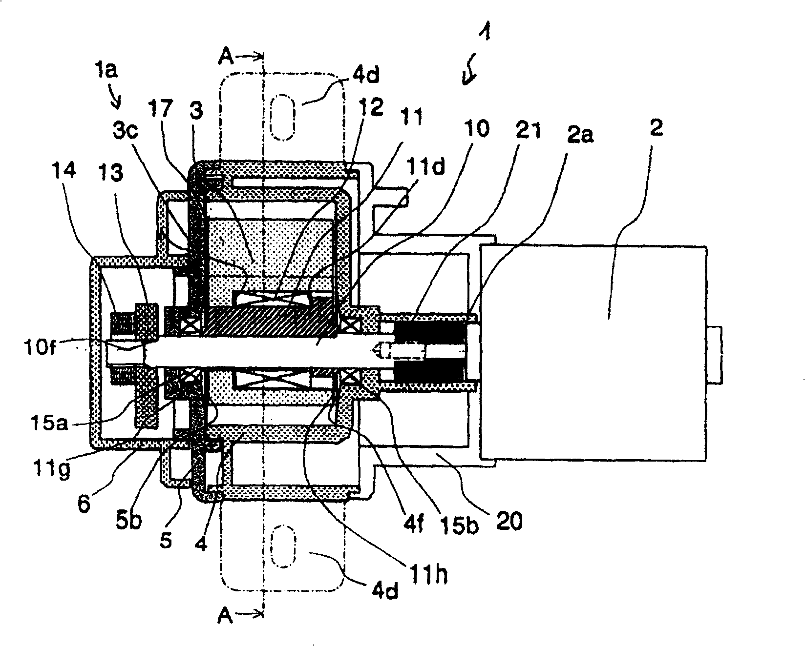
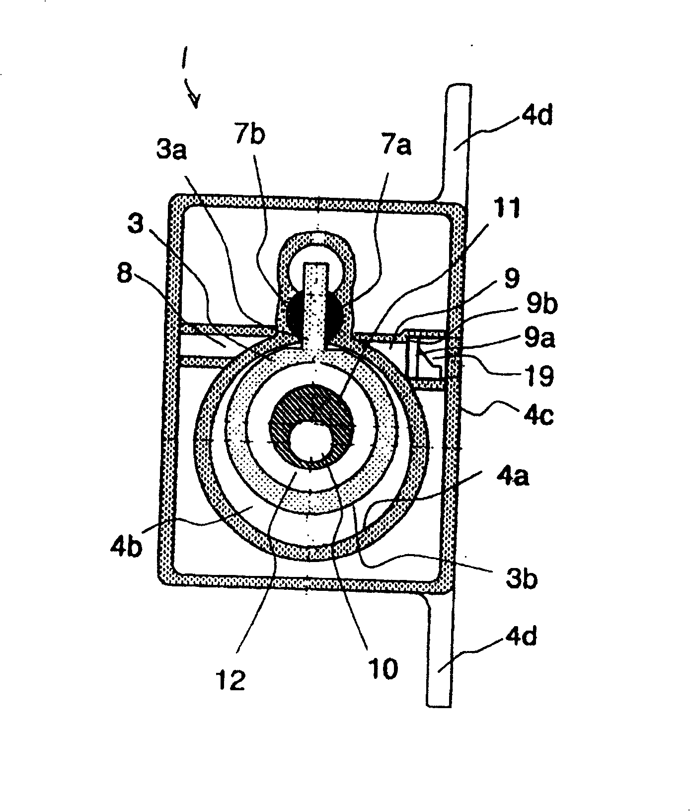
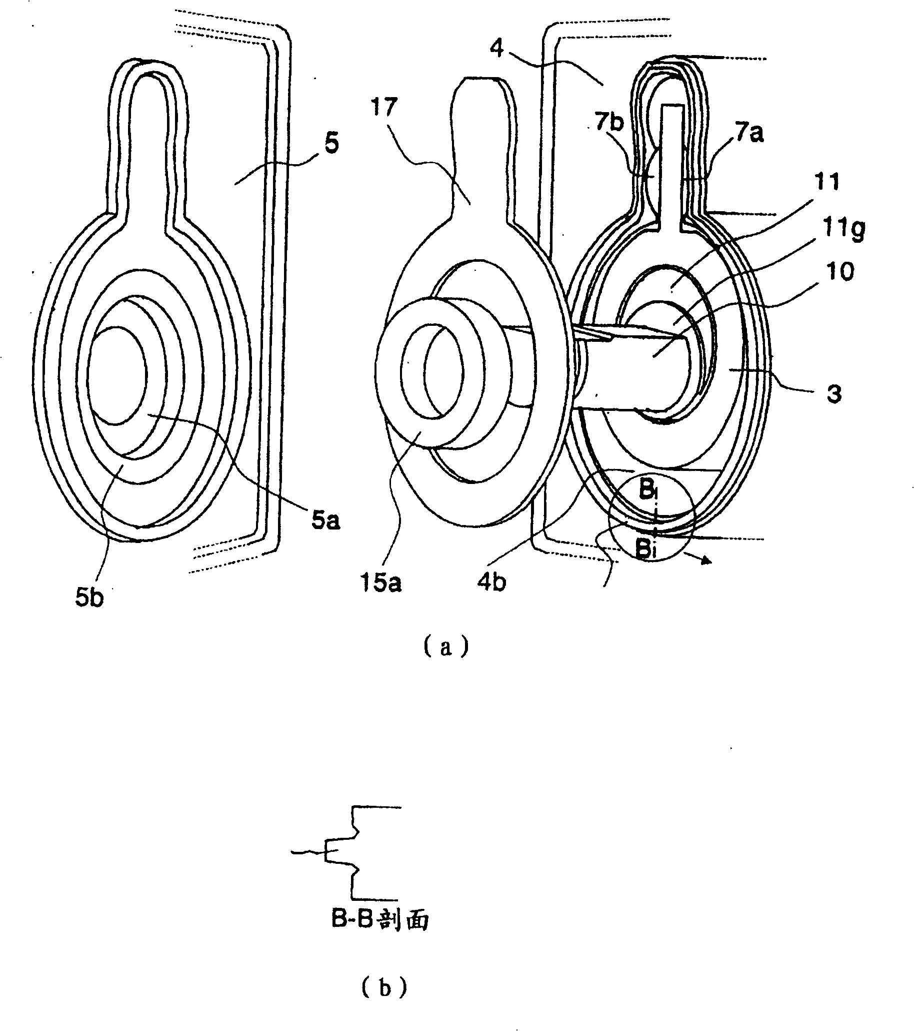
[0027] One embodiment of the portable vacuum pump of the present invention will be described below using the drawings. The vacuum pump shown in this embodiment is mainly used in a urine treatment device. figure 1 is a longitudinal sectional view showing a vacuum pump, figure 2 Yes figure 1 A-A sectional view of, image 3 Yes figure 1 An exploded perspective view of the main parts of the shown vacuum pump and its B-B sectional view, Figure 4 Yes figure 1 An exploded perspective view of the shaft end of the vacuum pump shown, Figure 5 is used for figure 1 An exploded perspective view of the shafting of the vacuum pump shown.

[0028] In the portable vacuum pump 1 , a vacuum pump body 1 a is connected to one side of a drive motor 2 through a coupling 21 . The motor 2 drives the vacuum pump main body 1a at a rotational speed of 4000 to 7000 rpm. The motor 2 has a diameter of about 30 mm and an axial length of about 35 mm. The motor 2 is driven by a dry battery or a se...


PUM


Abstract

The present invention makes the vacuum pump miniaturization and portability. In the hand-held vacuum pump 1, the main body 1 a of the vacuum pump in which the pump room 4 a is formed and the electric motor 2 are connected via the shaft coupling 21. The main body of the vacuum pump has the driving shaft 10. One ball bearing 15 b supporting the driving shaft is supported by the cylinder. The other ball bearing 15 a is sup ported by the flange 5 mounted hermetically at the cylinder. The end part of the cylinder at the side of the electric motor accommodates the shaft coupling, and is engaged with the end part of the electric motor so that the electric motor may support the cylinder.

Description

technical field [0001] The invention relates to a portable vacuum pump, in particular to a portable vacuum pump suitable for an automatic urination treatment device. Background technique [0002] Patent Document 1 describes an example of a suction device for urination for people who have difficulty moving to a place for urination by their own strength. In the urine suction device described in this gazette, a urine storage container is provided between a urine receiver and a suction pump as a suction source. Then, when urination is urinated into the urine receiver, the urination is detected, and suction is performed from the suction duct to the urine storage container. At this time, the suction pump controls the suction state based on the signal of the pressure sensor that detects the pressure change of the urine storage container. [0003] The suction pump uses multiple lightweight vacuum pumps. Examples of such vacuum pumps are described in Patent Document 2 and Patent D...

Claims


Application Information

Patent Timeline
Patent Type & Authority Patents(China)
IPC IPC(8): F04C18/356F04C25/02A61F5/44
Inventor 田添亘宫川良辅石塚义和田中哲也小豆畑喜芳衣目川勋
Owner HITACHI LTD
Why Eureka
Try Eureka