Capacitor with multiple elements for multiple replacement applications
What is Al technical title?
Al technical title is built by PatSnap Al team. It summarizes the technical point description of the patent document.
a technology of capacitors and elements, applied in the field of capacitors, can solve the problems of system failure, inoperableness, difficult and expensive maintenance of such inventory, etc., and achieve the effect of increasing the flexibility of replacing failed capacitors and safe connection
Active Publication Date: 2018-09-06
AMRAD MFG LLC
View PDF2 Cites 32 Cited by
Summary
Abstract
Description
Claims
Application Information
AI Technical Summary
This helps you quickly interpret patents by identifying the three key elements:
Problems solved by technology
Method used
Benefits of technology
Benefits of technology
[0015]An object of the disclosure to provide a capacitor having one or more of the foregoing objectives and which provides for safely making and maintaining connections thereto.
[0016]An object of the disclosu
Problems solved by technology
These capacitors have a finite life and sometimes fail, causing the system to become inoperative.
One option is for the serviceman to carry a large number of capacitors of different values in the service truck, but it is difficult and expensive to maintain such an inventory, especially because there can be a random need for several capacitors of the same value on the same day.
This is inefficient as the travel time to pick up parts greatly extends the overall time necessary to complete a repair.
This is extremely detrimental if there is a backlog of inoperative air-conditioning systems on a hot day.
This problem presents itself in connection with air-conditioning systems, but is also found in any situation where capacitors are used in association with motors and are replaced on service calls.
Efforts have been made to provide such a capacitor in the past, but they have not resulted in a commercially acceptable capacitor adapted for replacing capacitors having a wide rang
Method used
Image
Click on the blue label to locate the original text in one second.
Reading with bidirectional positioning of images and text.
Examples
Embodiment Construction
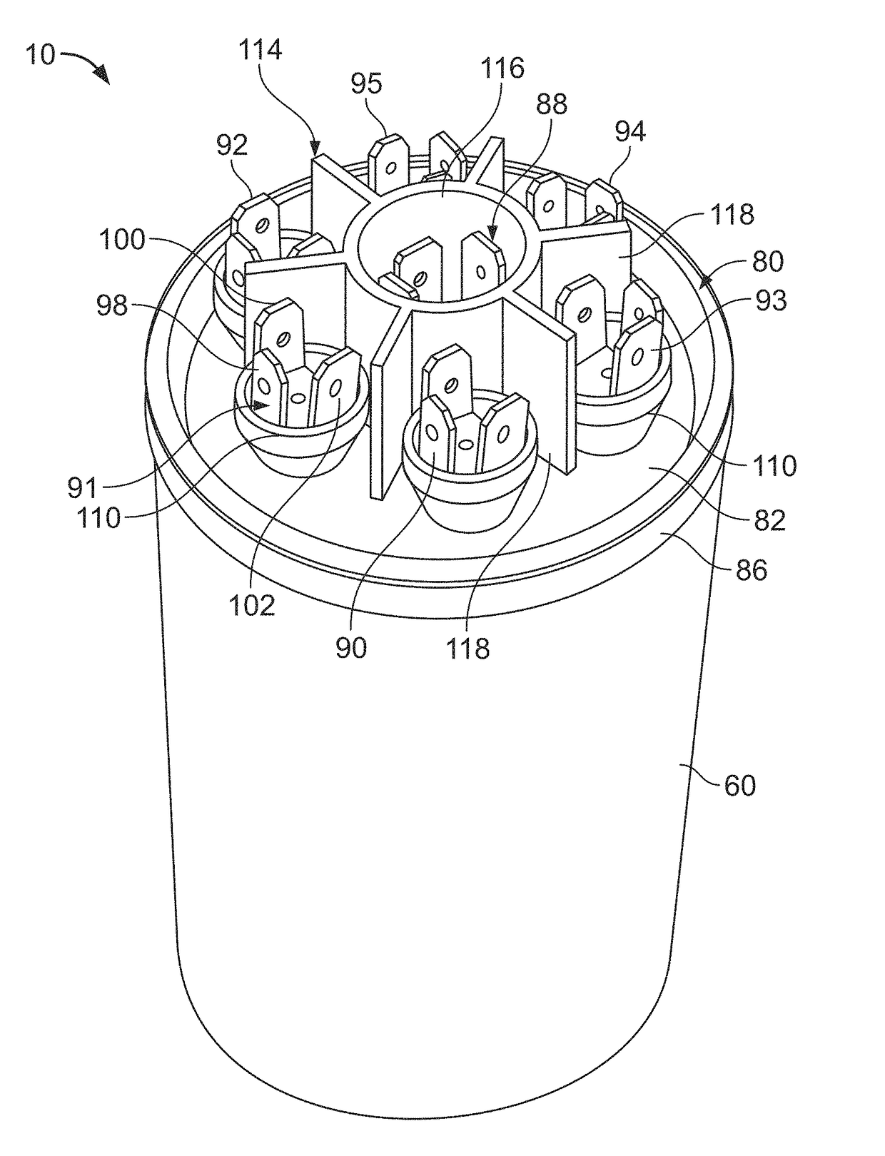
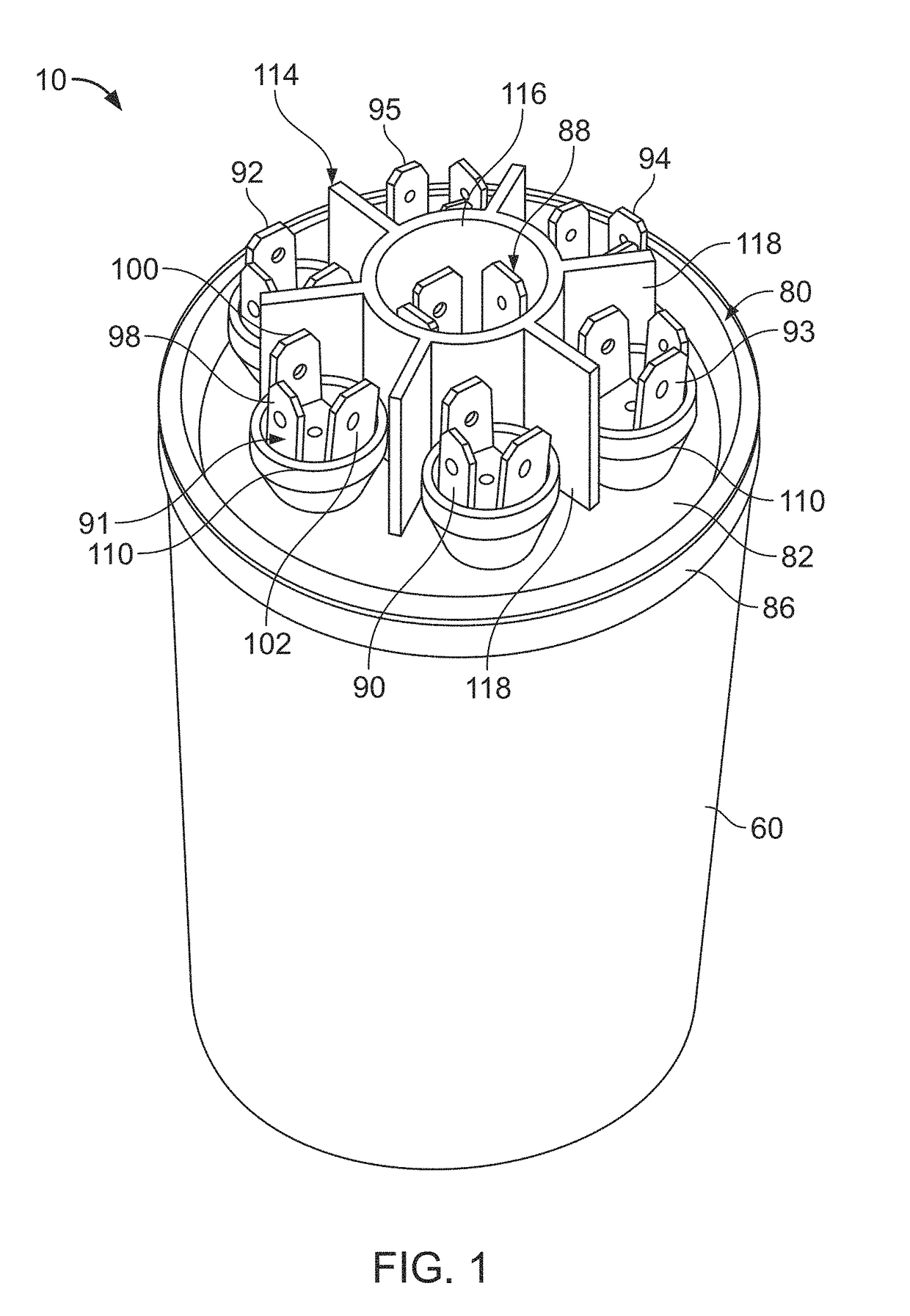
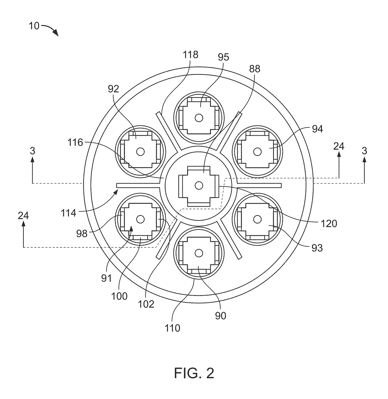
[0075]A capacitor 10 is shown in FIGS. 1-3, as well as in other Figures to be described below. The capacitor 10 is adapted to replace any one of a large number of capacitors. Therefore, a serviceman may carry a capacitor 10 on a service call and, upon encountering a failed capacitor, the serviceman can utilize the capacitor 10 to replace the failed capacitor with the capacitor 10 being connected to provide the same capacitance value or values of the failed capacitor.
[0076]The capacitor 10 has a capacitive element 12 having a plurality of capacitor sections, each having a capacitance value. The capacitive element 12 is also shown in FIGS. 4 and 5. In the preferred embodiment described herein, the capacitive element 12 has six capacitor sections 20-25. The capacitive element 12 is a wound cylindrical element manufactured by extension of the techniques described in my prior U.S. Pat. No. 3,921,041, my U.S. Pat. No. 4,028,595, my U.S. Pat. No. 4,352,145 and my U.S. Pat. No. 5,313,360, i...
PUM
Abstract
An apparatus includes a case having an elliptical cross-section capable of receiving a plurality of capacitive elements. One or more of the capacitive elements provide at least one capacitor having a first capacitor terminal and a second capacitor terminal. The apparatus also includes a cover assembly that includes a deformable cover mountable to the case, and, a common cover terminal having a contact extending from the cover. The cover assembly also includes at least three capacitor cover terminals, each of the at least three capacitor cover terminals having at least one contact extending from the deformable cover. The deformable cover is configured to displace at least one of the at least three capacitor cover terminals upon an operative failure of at least one of the plurality of the capacitive elements. The cover assembly also includes at least four insulation structures. One of the four insulation structures is associated with one of the at least three capacitor cover terminals. The apparatus also includes a first conductor capable of electrically connecting the first capacitor terminal of a capacitor provided by one of the plurality of capacitive elements to one of the at least three capacitor cover terminals and a second conductor capable of electrically connecting the second capacitor terminal of the capacitor provided by one of the plurality of capacitive elements to the common cover terminal.
Description
CLAIM OF PRIORITY[0001]This application is a continuation-in-part of and claims priority under 35 USC § 120 to U.S. application Ser. No. 15 / 220,505, filed Jul. 27, 2016, which is a continuation of and claims priority to U.S. application Ser. No. 14 / 506,213, filed Oct. 3, 2014, now U.S. Pat. No. 9,412,521, which claims priority under 35 USC § 119(e) to U.S. Provisional Patent Application Ser. No. 61 / 886,839, filed on Oct. 4, 2013, the entire contents of each of which are incorporated by reference herein. This application is also a continuation-in-part of and claims priority under 35 U.S.C. § 120 to U.S. application Ser. No. 13 / 966,593, filed on Aug. 14, 2013, now U.S. Pat. No. 8,891,224, which is a continuation of and claims priority to U.S. application Ser. No. 13 / 043,794, filed on Mar. 9, 2011, now U.S. Pat. No. 8,531,815, which is a continuation of and claims priority to U.S. application Ser. No. 12 / 283,297, filed Sep. 9, 2008, now U.S. Pat. No. 7,911,762, which is a continuation ...
Claims
Application Information
Patent Timeline
Application Date:The date an application was filed.
Publication Date:The date a patent or application was officially published.
First Publication Date:The earliest publication date of a patent with the same application number.
Issue Date:Publication date of the patent grant document.
PCT Entry Date:The Entry date of PCT National Phase.
Estimated Expiry Date:The statutory expiry date of a patent right according to the Patent Law, and it is the longest term of protection that the patent right can achieve without the termination of the patent right due to other reasons(Term extension factor has been taken into account ).
Invalid Date:Actual expiry date is based on effective date or publication date of legal transaction data of invalid patent.
