Variable magnification optical system, optical apparatus, imaging apparatus and method for manufacturing variable magnification optical system

a technology of optical system and magnification magnification, which is applied in the direction of optics, instruments, diffraction gratings, etc., can solve the problem of not being able to achieve high-speed focusing operation

Active Publication Date: 2018-09-13
NIKON CORP
View PDF3 Cites 0 Cited by
  • Summary
  • Abstract
  • Description
  • Claims
  • Application Information

AI Technical Summary

Problems solved by technology

H4-293007 is not intended to make a focusing group light in weight sufficiently and is not suitable for attain high speed focusing operation.

Method used


Image

  • Variable magnification optical system, optical apparatus, imaging apparatus and method for manufacturing variable magnification optical system
  • Variable magnification optical system, optical apparatus, imaging apparatus and method for manufacturing variable magnification optical system
  • Variable magnification optical system, optical apparatus, imaging apparatus and method for manufacturing variable magnification optical system

Examples


first example

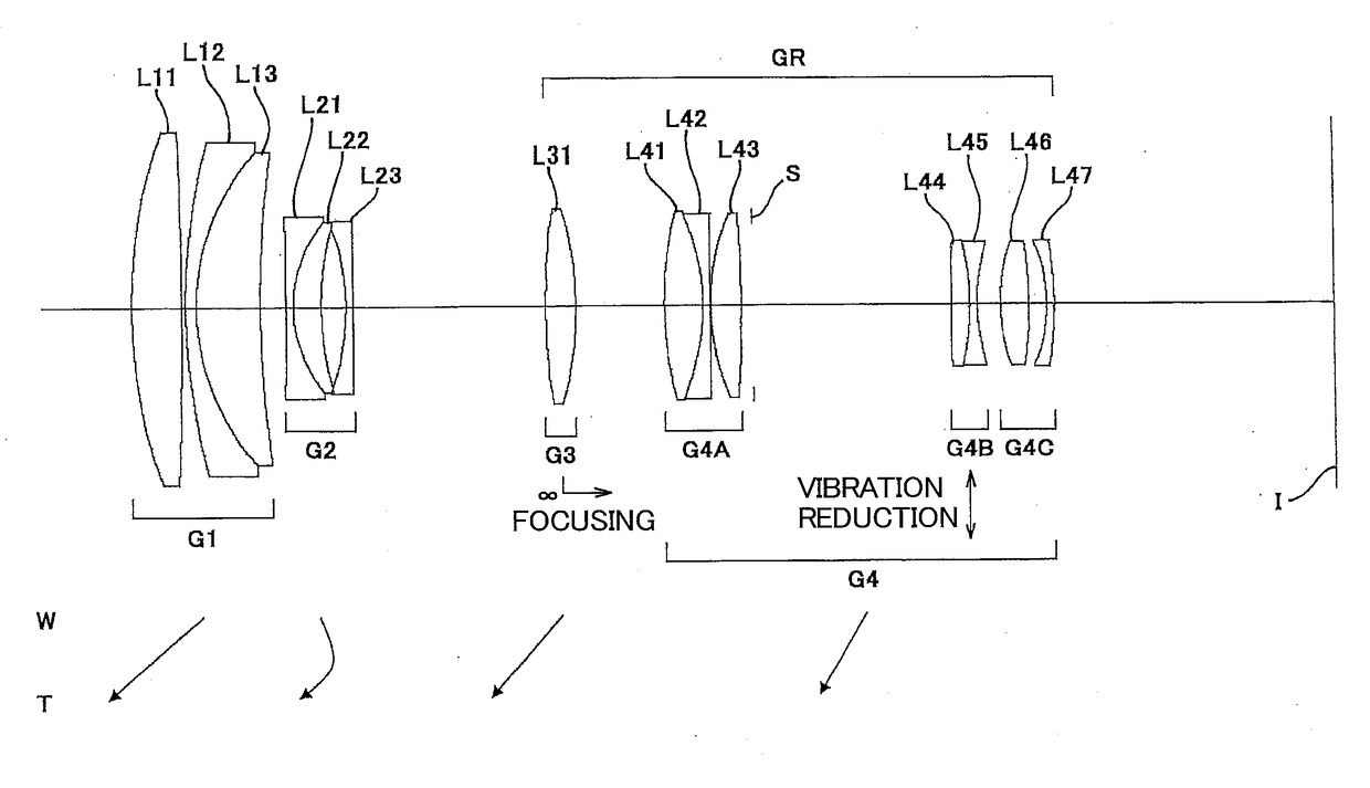
[0097]FIG. 1 is a sectional view of a variable magnification optical system according to a First Example. Note that each arrow in FIG. 1 and FIGS. 5, 9, 13, 17, 21, 25 and 29 as described later indicates moving trajectory of each lens group upon varying magnification from the wide angle end state (W) to the telephoto end state (T).

[0098]The variable magnification optical system according to the First Example is composed of, in order from an object side, a first lens group G1 having positive refractive power, a second lens group G2 having negative refractive power, and a rear group GR having positive refractive power. The rear group GR is composed of, in order from the object side, a third lens group G3 having positive refractive power, and a fourth lens group G4 having positive refractive power.

[0099]The first lens group G1 consists of, in order from the object side, a double convex positive lens L11, and a cemented positive lens constructed by a negative meniscus lens L12 having a ...

second example

[0124]FIG. 5 is a sectional view of a variable magnification optical system according to a Second Example.

[0125]The variable magnification optical system according to the Second Example is composed of, in order from an object side, a first lens group G1 having positive refractive power, a second lens group G2 having negative refractive power, and a rear group GR having positive refractive power. The rear group GR is composed of, in order from the object side, a third lens group G3 having positive refractive power, and a fourth lens group G4 having positive refractive power.

[0126]The first lens group G1 consists of, in order from the object side, a double convex positive lens L11, and a cemented positive lens constructed by a negative meniscus lens L12 having a convex surface facing the object side cemented with a positive meniscus lens L13 having a convex surface facing the object side.

[0127]The second lens group G2 consists of, in order from the object side, a cemented negative len...

third example

[0142]FIG. 9 is a sectional view of a variable magnification optical system according to a Third Example.

[0143]The variable magnification optical system according to the Third Example is composed of, in order from an object side, a first lens group G1 having positive refractive power, a second lens group G2 having negative refractive power, and a rear group GR having positive refractive power. The rear group GR is composed of, in order from the object side, a third lens group G3 having positive refractive power, and a fourth lens group G4 having positive refractive power.

[0144]The first lens group G1 consists of, in order from the object side, a double convex positive lens L11, and a cemented positive lens constructed by a negative meniscus lens L12 having a convex surface facing the object side cemented with a positive meniscus lens L13 having a convex surface facing the object side.

[0145]The second lens group G2 consists of, in order from the object side, a cemented negative lens ...


PUM


Abstract

Comprising a positive first lens group G1 disposed at a most object side, a negative intermediate group G2 disposed at an image side of the first lens group G1, a positive focusing group G3 disposed at an image side of the intermediate group G2, the focusing group G3 being moved upon focusing, and a positive image side group G4 disposed at an image side of the focusing group G3; upon varying magnification, a distance between the first lens group G1 and the intermediate group G2, a distance between the intermediate group G2 and the focusing group G3 and a distance between the focusing group G3 and the image side group G4 being varied; and a predetermined conditional expression being satisfied. Whereby a variable magnification optical system having excellent optical performance and a focusing lens group reduced in weight in order to attain high speed focusing operation, and others are provided.

Description

TECHNICAL FIELD[0001]The present invention relates to a variable magnification optical system, an optical apparatus, an imaging apparatus and a method for manufacturing the variable magnification optical system.BACKGROUND ART[0002]There has been proposed a variable magnification optical system that is suitable to be used for a photographic camera, an electronic still camera, a video camera and the like. For example, please refer to a Japanese Patent application Laid-Open Gazette No. H4-293007. However, a variable magnification optical system as disclosed in the Japanese Patent application Laid-Open Gazette No. H4-293007 is not intended to make a focusing group light in weight sufficiently and is not suitable for attain high speed focusing operation.PRIOR ART REFERENCEPatent Document[0003]Patent Document 1: Japanese Patent application Laid-Open Gazette No. H4-293007.SUMMARY OF THE INVENTION[0004]According to a first aspect of the present invention, there is provided a variable magnif...

Claims


Application Information

Patent Timeline
Patent Type & Authority Applications(United States)
IPC IPC(8): G02B15/20G02B27/64
CPCG02B15/20G02B27/646G02B15/144113G02B15/145113
Inventor MACHIDA, KOSUKE
Owner NIKON CORP
Why Eureka
Try Eureka