Mulcher

a mulcher and rotor technology, applied in the field of mulchers, can solve the problems that the gearbox assigned to the chopping blade rotor is at risk, and the slip clutch between the chopping blade rotor and the gearbox which could dampen the effects of impacts cannot be used, so as to achieve the effect of being easily protected from the effects

Active Publication Date: 2018-09-20
BRAUN MASCHFAB
View PDF10 Cites 0 Cited by
  • Summary
  • Abstract
  • Description
  • Claims
  • Application Information

AI Technical Summary

Benefits of technology

[0006]It is an advantage of the invention that it eliminates the need for complicated components to transmit a rotational movement from the tractor to the chopping blade rotors by way of several gearboxes on the mulcher. The electric drives assigned individually to the chopping blade rotors can also be more easily protected from the effects of accidents.
[0007]In a preferred embodiment of the invention, the devices for controlling the electric drive comprise means for determining the rotational angle of the rotors of the electric motors. When there is a rigid connection between the chopping blade rotor and the rotor of the electric motor by means of a rotor shaft, the rotational position of the individual chopping blade rotor can be determined by the control device and can be changed if necessary in such a way that a collision between the individual chopping blades of the chopping blade rotors, which overlap in the areas of their rotation, is avoided.
[0008]In particular, the devices for con

Problems solved by technology

When accidents occur, especially collisions of the individual blades of the chopping blade rotors with obstacles on the ground, the gearboxes assigned to the chopping blade rotors are put at risk.

Method used


Image

  • Mulcher
  • Mulcher
  • Mulcher

Examples


Embodiment Construction

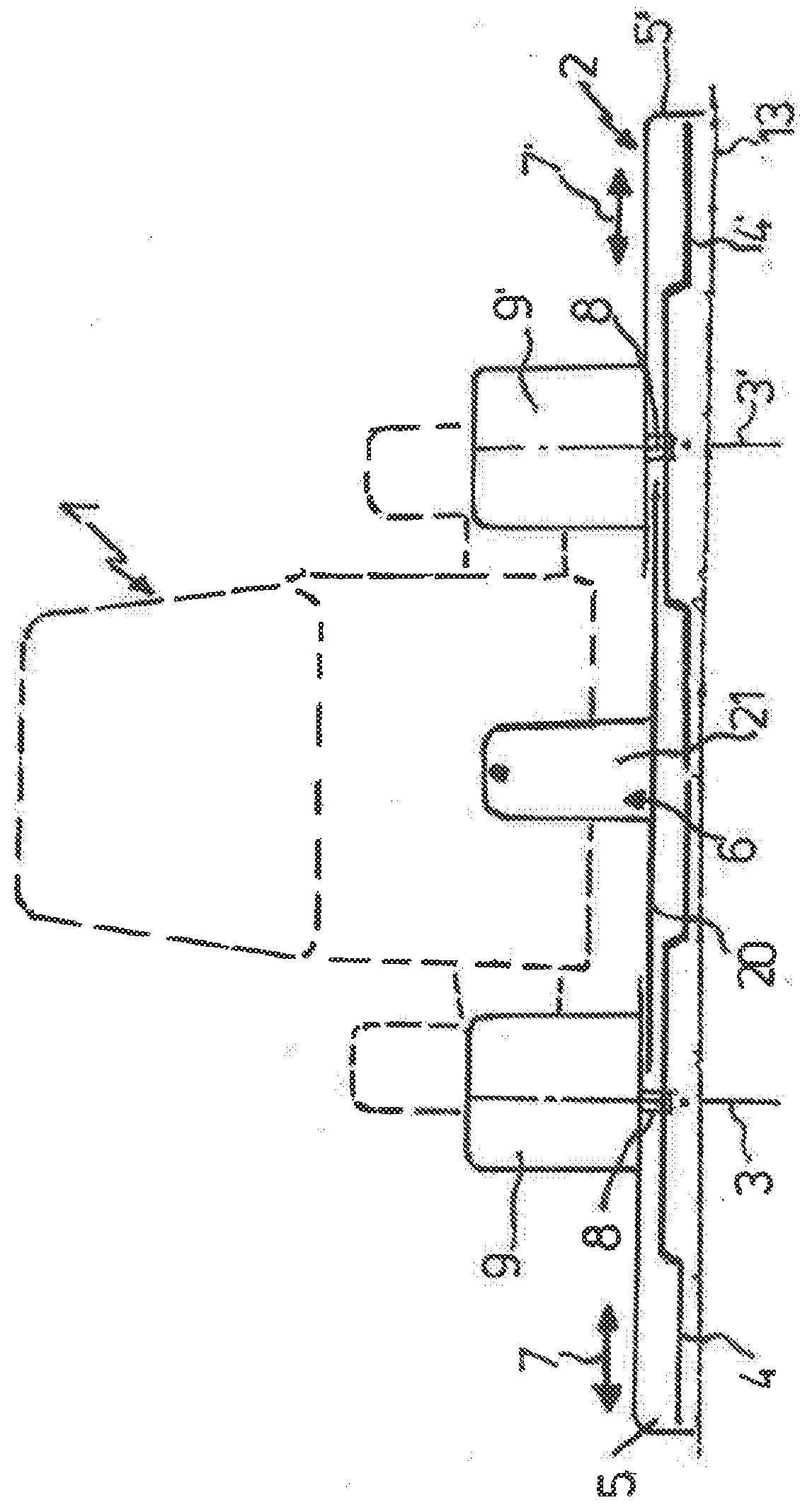
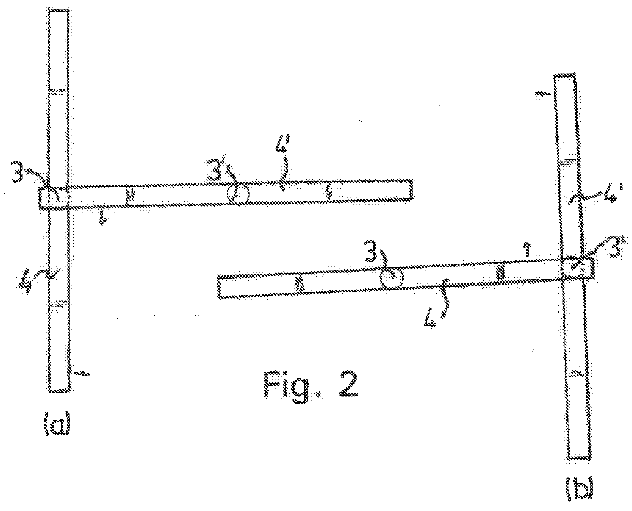
[0022]An apparatus (mulcher) for keeping down the groundcover between parallel rows of plants, especially between rows of wine grape or fruit plants, can be coupled to a tractor 1 of suitably narrow dimensions and comprises a flat housing 2, open at the bottom, in which chopping blade rotors 4, 4′ rotate around axes 3, 3′ in a single plane parallel to the ground 13. Each of the chopping blade rotors 4, 4′ comprises two chopping blades pointing in opposite directions.

[0023]The housing 2 comprises two housing parts 5, 5′, which are shiftable relative to a carrier device 6 in a direction perpendicular to the parallel plant rows, as shown by the arrows 7, 7′, the carrier device 6 being supported on the ground 13 by rollers (not shown). The carrier device 6 allows the apparatus to be connected to the tractor 1.

[0024]Hydraulic cylinders (not shown) for shifting the housing parts 5, 5′ as shown by the arrows 7, 7′ and rails for the guidance and support of the housing parts 5, 5′ are instal...


PUM


Abstract

An apparatus (mulcher) for keeping down groundcover between parallel rows of plants, especially rows of wine grape or fruit plants, with two chopping blade rotors rotating in one and the same plane, each around an axis perpendicular to the ground. The distance between the rotational axes is adjustable in a direction perpendicular to the plant rows even though the rotational areas of the chopping blade rotors may overlap. A separate electric motor is assigned to each of the chopping blade rotors, and devices are provided to control the electric motor so that that collisions between the chopping blade rotors are avoided.

Description

BACKGROUND OF THE INVENTION[0001]The invention pertains to an apparatus for keeping down the groundcover between parallel rows of plants, in particular rows of wine grape or fruit plants, with two chopping blade rotors rotating in one and the same plane, each around an axis perpendicular to the ground, wherein the distance between the rotational axes perpendicular to the plant rows is adjustable even though the areas in which the chopping blade rotors rotate may overlap.[0002]Apparatuses of this type, so-called mulchers, are known through use. The chopping blade rotors of these known mulchers, intended to be coupled to small tractors, are driven by a shaft connected to the tractor. The rotation of this power take-off shaft is first transmitted to a hex shaft by a central gearbox of the mulcher and then by the hex shaft to the gearboxes of the mulcher assigned to the chopping blade rotors. When the distance between the rotational axes of the chopping blade rotors is adjusted, these g...

Claims


Application Information

Patent Timeline
IPC IPC(8): A01D34/82A01D34/66A01D34/78
CPCA01D34/828A01D2101/00A01D34/78A01D34/66A01D34/005A01D34/661
Inventor BRAUN, STEFAN JACOB
Owner BRAUN MASCHFAB
Why Eureka
Try Eureka