Clamping device for being connected to frame of bicycle carry rack

a technology of bicycle carry rack and clamping device, which is applied in the direction of supplementary fittings, cycle stands, fastening means, etc., can solve problems such as determining skill levels

Inactive Publication Date: 2018-09-27
KING RACK INDUSTRIAL CO LTD
View PDF0 Cites 6 Cited by
  • Summary
  • Abstract
  • Description
  • Claims
  • Application Information

AI Technical Summary

Benefits of technology

[0010]The advantages of the present invention are that the first clamp unit clamps the frame of bicycle carry rack by way of pushing the frame through the entrance, so that the users can easily complete the action.

Problems solved by technology

Nevertheless, to clamp the first clamp unit to the frame in the reverse direction needs a certain level of skill, and the beginners need time to practice to easily finish the action.

Method used


Image

  • Clamping device for being connected to frame of bicycle carry rack
  • Clamping device for being connected to frame of bicycle carry rack
  • Clamping device for being connected to frame of bicycle carry rack

Examples


Embodiment Construction

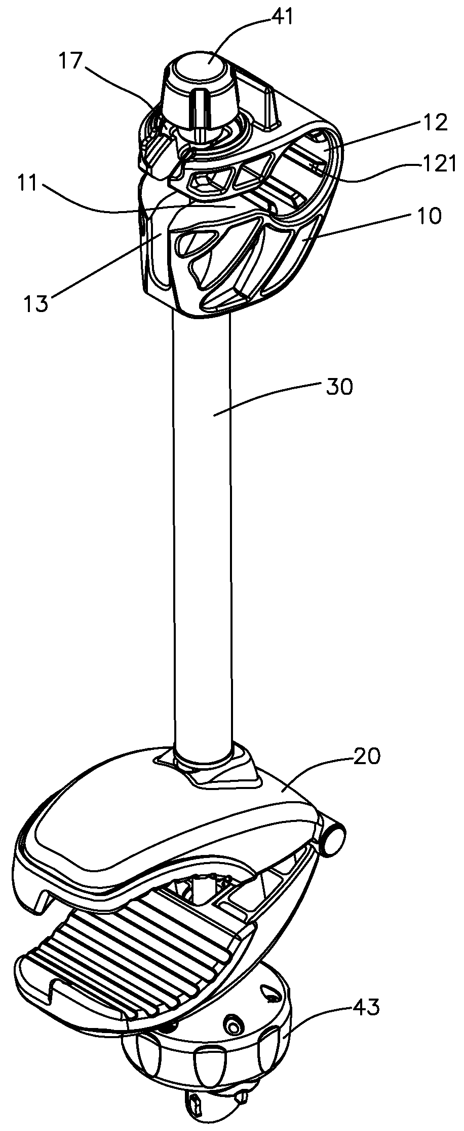
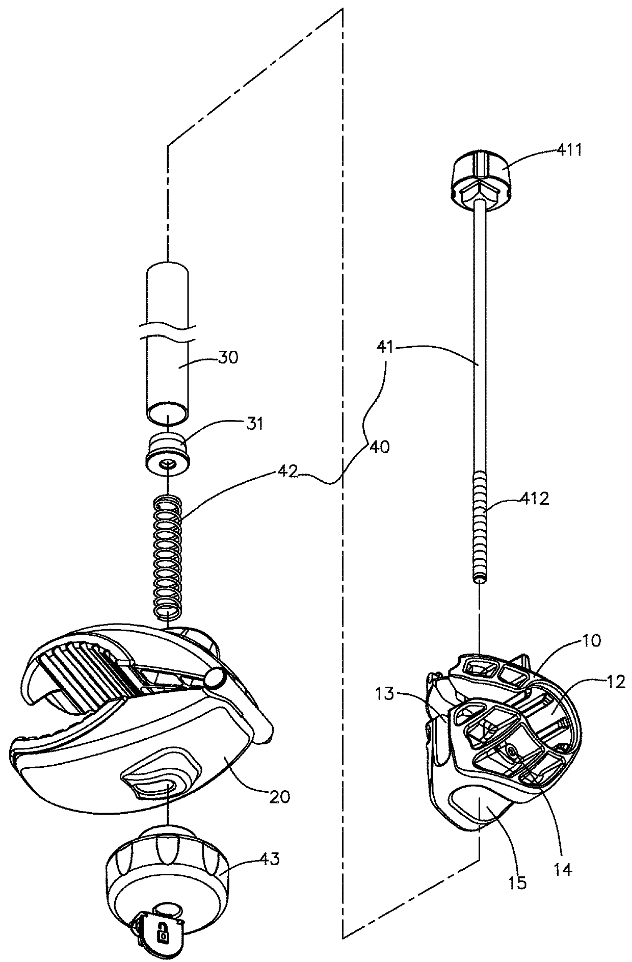
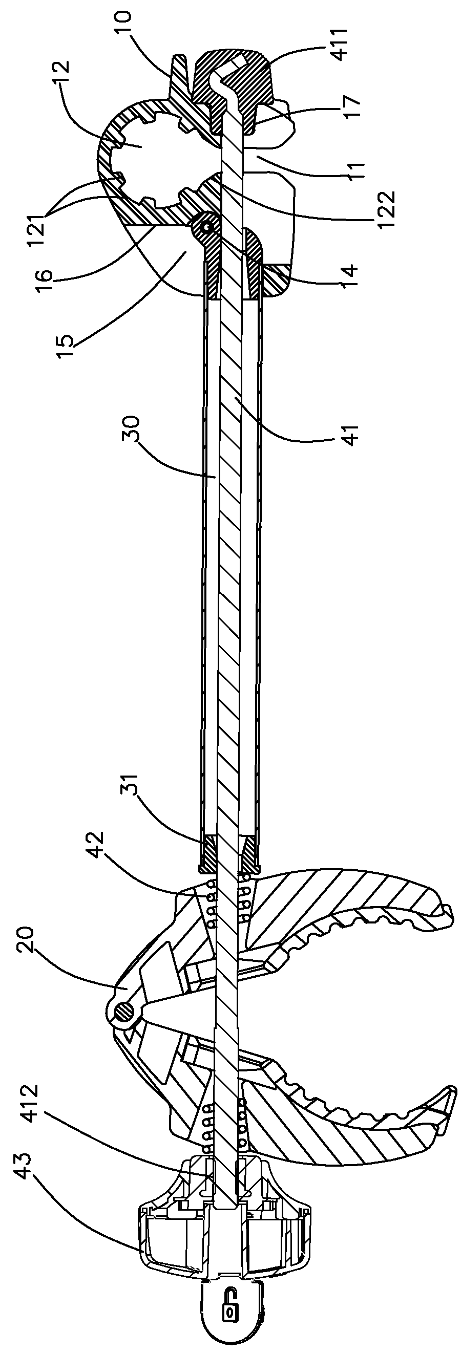
[0025]Referring to FIGS. 1 to 3, the clamping device for a bicycle carry rack of the present invention comprises a tube 30, a first clamp unit 10, a second clamp unit 20 and a fastening unit 40. The first clamp unit 10 and the second clamp unit 20 are respectively located on two ends of the tube 30, and an end member 31 is connected to one end of the tube 30 and is located close to the second clamp unit 20. The fastening unit 40 includes a pin 41 which includes a head 411 and a threaded end 412 respective formed on two ends thereof. The pin 41 extends through the first clamp unit 10, the tube 30, the second clamp unit 20, a spring 42, the second clamp unit 20 and is threadedly connected to a knob 43 by the threaded end 412. The spring 42 is connected to the second clamp unit 20 and used to allow the second clamp unit 20 to proceed clamping and opening actions. The fastening unit 40 is connected between the first and second clamp units 10, 20.

[0026]As shown in FIGS. 3, 5 and 6, the f...


PUM


Abstract

A clamping device for a bicycle carry rack includes a tube with a first clamp unit and a second clamp unit respectively located on two ends thereof. A fastening unit includes a pin which is connected between the first and second clamp units. The first clamp unit includes a clamping slot and an entrance which communicates with the clamping slot. The entrance guides the frame of a bicycle carry rack into the clamping slot. The first clamp unit has a restriction recess for receiving a head of the pin, the other of the pin is threadedly connected to a knob. The head of the pin is removed from the restriction recess when the second clamp clamps, and the first clamp unit is pivotable relative to the pin, and to clamp the frame of the bicycle carry rack by its clamping slot via the entrance.

Description

BACKGROUND OF THE INVENTION1. Fields of the Invention[0001]The present invention relates to a clamping device for quickly being connected to the frame of a bicycle carry rack.2. Descriptions of Related Art[0002]The conventional bicycle carry rack is usually connected to a hitch ball on rear end of a vehicle, and the bicycle carry rack has a clamp device that has one end secured to a frame of the bicycle carry rack, and the other end of the clamp device holds the top tube, for example, of a bicycle so that the bicycle is carried with the vehicle. The conventional clamp device includes a tube, a first clamp unit for clamping the frame of the bicycle carry rack, a second clamp unit for holding the bicycle, and a fastening unit. The first and second clamp units are connected to two ends of the tube, and the fastening unit keeps the first and second clamp units together. The tube of the clamp unit has two end members respectively connected to two ends thereof. The two ends of the tube re...

Claims


Application Information

Patent Timeline
Patent Type & Authority Applications(United States)
IPC IPC(8): F16B2/12
CPCB60R9/10F16B2/02F16B2/12B62H2700/00B60R9/06B62H3/02F16B2/08F16B2/065F16B2/10
Inventor WANG, CHIU KUEI
Owner KING RACK INDUSTRIAL CO LTD
Why Eureka
Try Eureka