Sealing device

a sealing device and sealing technology, applied in the direction of engine seals, mechanical devices, engine components, etc., can solve the problems of short sealing device, invading foreign matter, and reducing sealing performance, so as to reduce the operation efficiency of rotational members and easy to find

Inactive Publication Date: 2018-09-27
JTEKT CORP
View PDF8 Cites 4 Cited by
  • Summary
  • Abstract
  • Description
  • Claims
  • Application Information

AI Technical Summary

Benefits of technology

[0033]With the sealing device, when the predetermined threshold is set to a change value of the inductance at the time when the inductance decreases to around a value at which the seal performance of the sealing device is impaired, it is possible to easily find that the sealing device nears its use limit.
[0034]With the present disclosure, in terms of a sealing device including a seal lip having a sealing surface making close contact with a rotating shaft, it is possible to inspect a deformation degree of the seal lip caused due to wearing-out of the sealing surface without reducing operation efficiency of a rotational member.

Problems solved by technology

When the seal lip deforms by a predetermined amount due to the wearing-out of the sealing surface, a contact pressure between the sealing surface and the rotating shaft becomes insufficient, so that seal performance is decreased, thereby causing an invasion of a foreign matter into an annular space or an outflow of a lubricant to outside the annular space.
However, in such a method, a replacement cycle of the sealing device is short, so that it takes time to perform maintenance of the sealing device.
Further, if an abnormal deformation occurs in the seal lip before a predetermined replacement timing comes, it is difficult to restrain the invasion of a foreign matter into the annular space and the outflow of the lubricant to outside the annular space.
This accordingly decreases operation efficiency of the rotational member.
In a case where the conductive member and the reference member are bold metal wires, deformation of the seal lip is disturbed by their rigidities.
As a result, the deformation degree of the seal lip cannot be inspected accurately.
In contrast, when the metal wire having a section with a diameter that is the predetermined diameter or less is used as the conductive member and the reference member, a possibility to disturb the deformation of the seal lip associated with wearing-out of the sealing surface is low because the rigidity of the metal wire is low.
As a result, the deformation degree of the seal lip cannot be inspected accurately.
In contrast, when the metal wire having a section with a diameter that is the predetermined diameter or less is used as the conductive member, a possibility to disturb deformation of the seal lip associated with wearing-out of the sealing surface is low because the rigidity of the metal wire is low.

Method used


Image

  • Sealing device
  • Sealing device
  • Sealing device

Examples


first embodiment

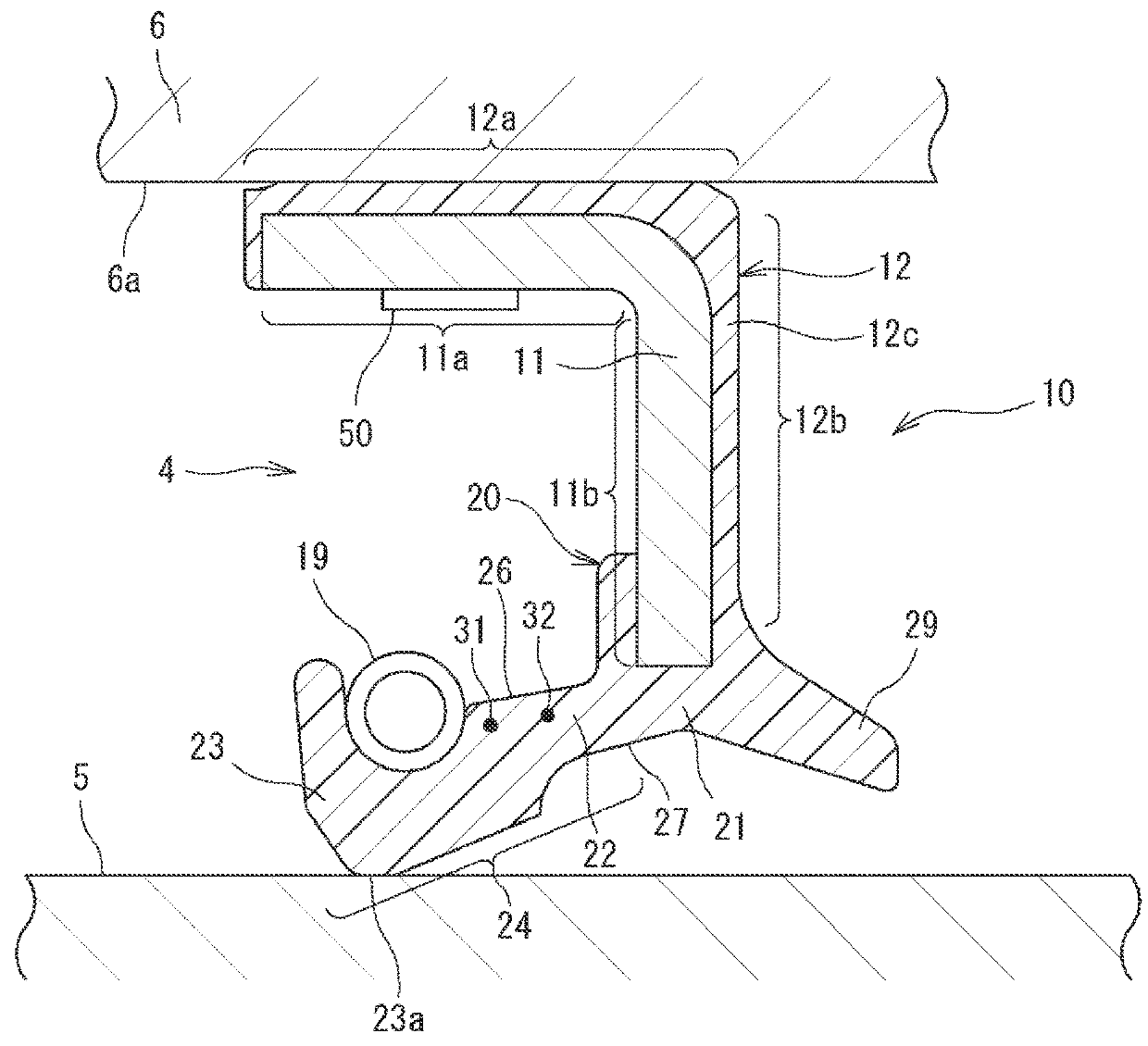
[0045]A sealing device 10 according to the present disclosure is an oil seal as an example. FIG. 1 is a sectional view of the sealing device 10. The sealing device 10 is provided together with a rolling bearing (not shown) configured to support a shaft 5 with respect to a housing 6. The housing 6 has a cylindrical inner peripheral surface 6a. An annular space 4 is formed radially inward of the cylindrical inner peripheral surface 6a, between the housing 6 and the shaft 5. The rolling bearing is provided at a predetermined position in the annular space 4, and respective sealing devices 10 are provided on the opposite sides of the rolling bearing in an axial direction. The shaft 5 is a rotatable rotating shaft, for example. The housing 6 corresponds to an example of an “outer member” in the present disclosure.

[0046]The shaft 5 is made of a soft magnetic material. The soft magnetic material is iron, for example. The shaft 5 is assembled concentrically to the cylindrical inner periphera...

second embodiment

[0089]FIG. 8 is a view to describe a principle to detect deformation of the seal lip 24 of the present disclosure. In FIG. 8, the seal lip 24 is indicated by a continuous line and an alternate long and two short dashes line. The seal lip 24 in the continuous line indicates a state before the sealing surface 23a is worn out. The seal lip 24 in the alternate long and two short dashes line indicates a state where the sealing surface 23a has been worn out.

[0090]Referring to FIG. 8, when the sealing surface 23a is worn out, the seal lip 24 deforms toward the shaft 5 side, starting from the fixed portion 21. Due to the deformation of the seal lip 24, the interval between the first conductive member 31 and the shaft 5 is decreased by a distance d.

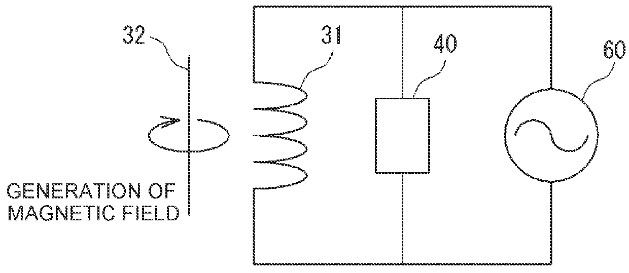
[0091]Since a voltage is applied to the first conductive member 31, a magnetic field is generated around the first conductive member 31. When the interval (distance) between the first conductive member 31 and the shaft 5 changes, magnetic resistan...


PUM


Abstract

A sealing device includes a conductive member integrated with a seal lip along a circumferential direction of the seal lip and configured such that a voltage is applied to the conductive member, and a reference member provided at a predetermined interval with respect to the conductive member. A deformation degree of the seal lip is inspected such that a change of an inductance of the conductive member associated with a change of the interval between the conductive member and the reference member is detected by a detection unit.

Description

INCORPORATION BY REFERENCE[0001]The disclosure of Japanese Patent Application No. 2017-054627 filed on Mar. 21, 2017 and Japanese Patent Application No. 2017-054866 filed on Mar. 21, 2017, each including the specification, drawings and abstract, is incorporated herein by reference in its entirety.BACKGROUND1. Technical Field[0002]The disclosure relates to a sealing device.2. Description of Related Art[0003]A sealing device is used for a rotational member in an industrial product or an industrial machine, in order to prevent an invasion of a foreign matter into a space between a rotating shaft and a housing and an outflow of a lubricant such as grease. An example of the sealing device is a sealing device including a seal lip that slidably makes close contact with a rotating shaft. An oil seal has been widely used as such a sealing device.SUMMARY[0004]When a sealing surface on an inner periphery of the seal lip makes close contact with an abutting surface of a rotating shaft, the seal...

Claims


Application Information

Patent Timeline
Patent Type & Authority Applications(United States)
IPC IPC(8): F16J15/3296F16J15/3204
CPCF16J15/3296F16J15/3204F16J15/3208F16J15/3212
Inventor SHIMIZU, YOHEI
Owner JTEKT CORP
Why Eureka
Try Eureka