Cleaning apparatus

a technology of cleaning apparatus and cleaning fluid, which is applied in the direction of cleaning process and equipment, cleaning using liquids, gearing, etc., can solve the problems of increasing the cleaning time, and affecting the cleaning effect, so as to reduce the consumption of cleaning fluid and electric power, reduce the cleaning time, and save the effect of cleaning tim

Active Publication Date: 2018-10-04
SHIBUYA MASHINARII
View PDF1 Cites 11 Cited by
  • Summary
  • Abstract
  • Description
  • Claims
  • Application Information

AI Technical Summary

Benefits of technology

[0013]According to such configurations, it is possible to suppress consumption of cleaning fluid and electric power. Moreover, it is possible to perform efficient cleaning of objects to be cleaned in a reduced cleaning time.

Problems solved by technology

For that reason, there is risk that cleaning effect differs between in an area which comes into contact with the cleaning fluid and in an area which will not, in an object to be cleaned (a tank) so that imperfect cleaning may occur in the area which will not come into contact with the cleaning fluid.
Moreover, as the distance from the nozzle increases, in addition to that a spacing between the movement trajectories of cleaning fluid increases, the cleaning pressure decreases making it difficult to achieve sufficient cleaning so that there are risks of nonuniform cleaning and imperfect cleaning.
Further, even if the inner surface of the tank is clean excepting some areas, if there is an area which is difficult to be cleaned (defective cleaning), since it is necessary to perform cleaning by spraying a large amount of cleaning fluid from the nozzle in accordance with the area difficult to be cleaned, increase the cleaning time, or increase the number of cleaning, a problem exists in that the cleaning time increases and also the use amount of the cleaning fluid increases.
Further, performing cleaning of objects to be cleaned having various shapes by spraying the cleaning fluid from the nozzle under the same condition will result in spraying the cleaning fluid from the nozzle oriented upward even when cleaning for example a cylindrical pot with an open top face, causing unnecessary consumption of cleaning fluid and waste in cleaning time, and the cleaning effect decreases.

Method used


Image

  • Cleaning apparatus
  • Cleaning apparatus
  • Cleaning apparatus

Examples


Embodiment Construction

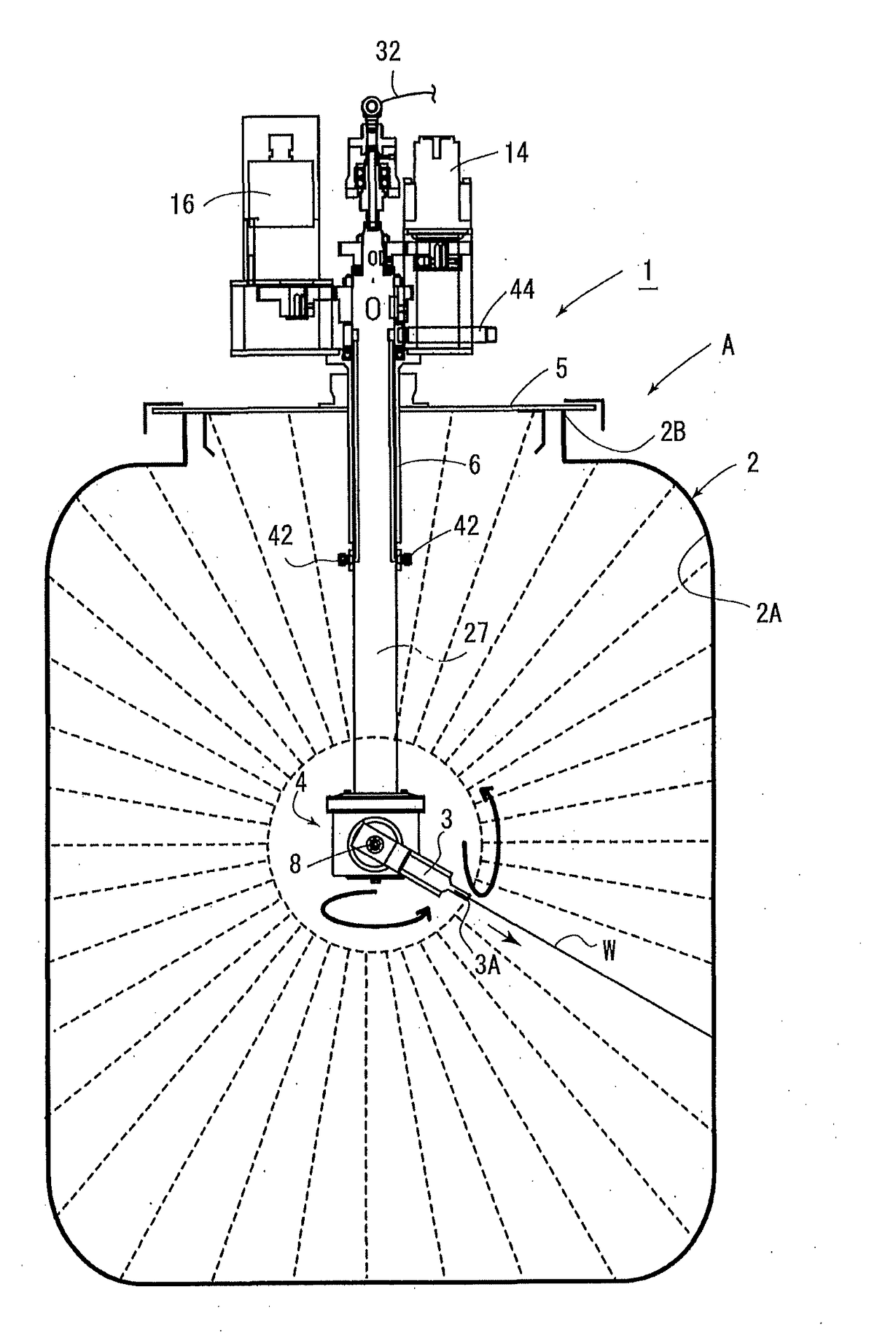
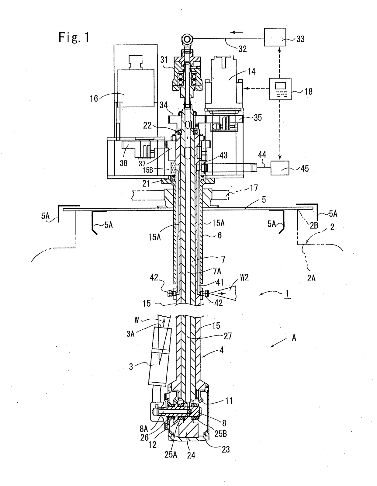
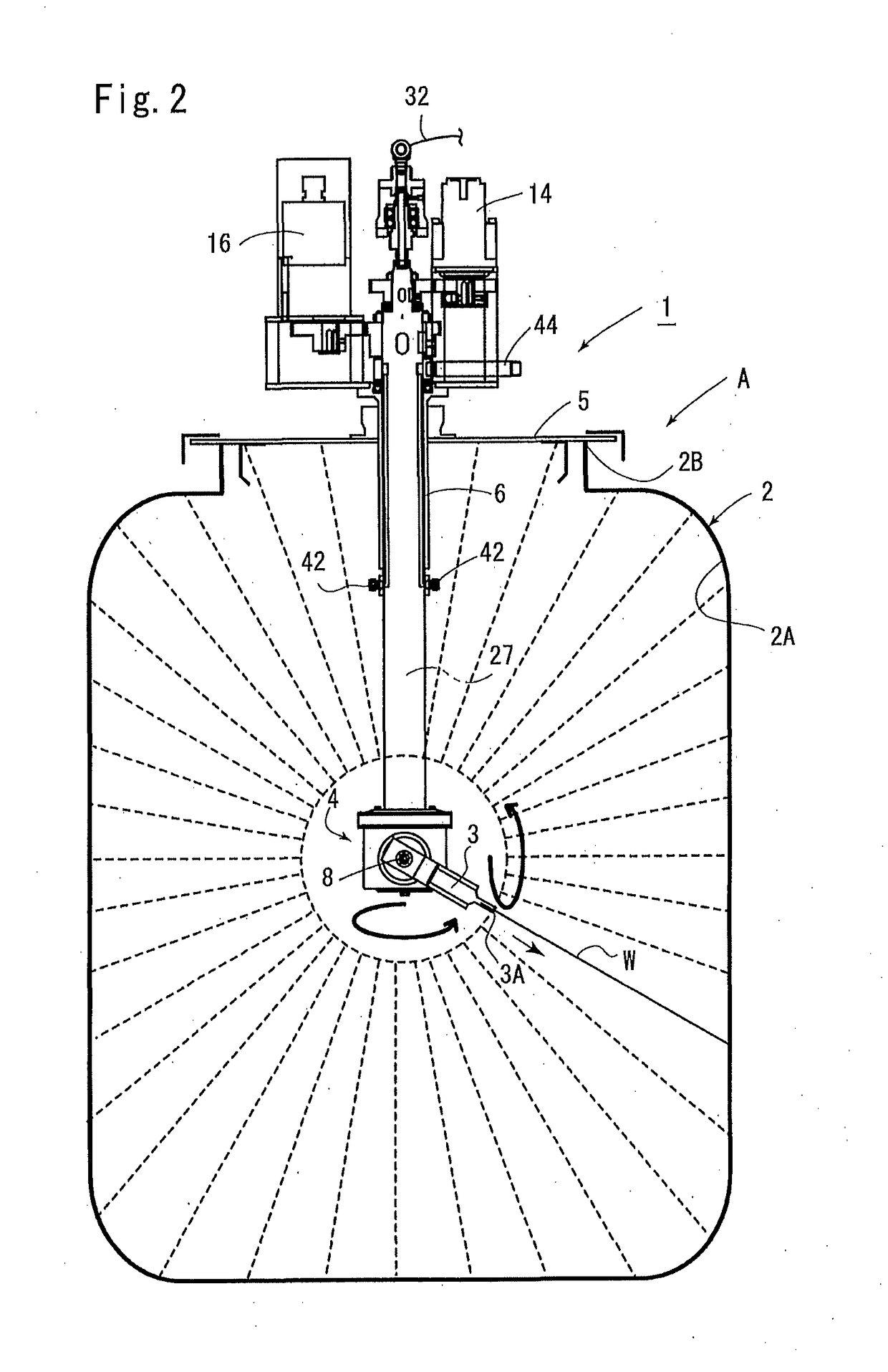
[0021]Hereinafter, describing the present invention on an illustrated embodiment, in, FIGS. 1 to 3, a reference numeral 1 indicates a cleaning apparatus for cleaning an inner surface 2A of a tank 2 as an object to be cleaned. The cleaning apparatus 1 includes: a cleaning unit 4 for spraying cleaning fluid W (water) from a nozzle 3 toward the inner surface 2A of the tank 2; a tubular support member 6 for rotatably supporting the cleaning unit 4 and being connected with a lid 5 at an upper part of its outer peripheral portion; a first motor 14 for rotating an inner tube 7; a second motor 16 for rotating an outer tube 15; a lift mechanism 17 for supporting the lid 5 and the cleaning unit 4 via the support member 6, and moving them up and down when required; and a control device 18 for controlling the operations of both the motors 14 and 16 and the lift mechanism 17.

[0022]Here, first, outline operation steps when cleaning the tank 2 will be described. When the tank 2 as the object to be...


PUM


Abstract

A cleaning apparatus 1 includes: a pivot rotary shaft 8 attached with a nozzle 3; a first motor 14 for revolving and rotating the pivot rotary shaft 8 via an inner tube 7 and bevel gears 11 and 12; a second motor 16 for solely rotating an outer tube 15; and a control device 18 for controlling the operation of both the motors 14 and 16. The outer tube 15, and the pivot rotary shaft 8 and the nozzle 3 are operated together via the bevel gears 11 and 12. The first motor 14 is operated with the cleaning fluid W being sprayed from the nozzle 3 to rotate the nozzle 3 and the pivot rotary shaft 8, and the second motor 16 is operated at a required rotational frequency. Then, as a result of the outer tube 15 being rotated, the nozzle 3 is revolved while being inclined in a required direction without being rotated. This makes it possible to preferentially spray the cleaning fluid W onto required areas of the inner surface 2A of the tank 2. It is possible to suppress consumption of the cleaning fluid W and electric power, and efficiently clean the inner surface 2A of the tank 2.

Description

BACKGROUND OF THE INVENTIONField of the Invention[0001]The present invention relates to a cleaning apparatus, and more particularly to, for example, a cleaning apparatus configured such that a nozzle is caused to enter into a tank and a cleaning fluid is sprayed from the nozzle to clean the inner surface of the tank.Description of the Related Art[0002]Conventionally, a cleaning apparatus in which a nozzle is caused to enter into a tank, etc. to clean the inner surface of the tank has been publicly known (for example, Japanese Patent No. 4636956).[0003]Such a conventional cleaning apparatus includes a rotary shaft which acts as a driving side, a pivot rotary shaft which is disposed at a lower end part thereof, and a nozzle attached to the pivot rotary shaft, in which the rotary shaft and the pivot rotary shaft are operated together by a pair of bevel gears. And upon performing cleaning, a cleaning fluid is sprayed from the nozzle, and the rotary shaft is rotated so that the pivot rot...

Claims


Application Information

Patent Timeline
Patent Type & Authority Applications(United States)
IPC IPC(8): B08B9/08B05B13/06B08B3/02
CPCB08B9/0813B05B13/0636B05B13/069B08B3/024F16H1/14B08B2209/08B08B9/093B08B9/0936
Inventor KITAMURA, TAKAHITODAIJO, MASAHIRO
Owner SHIBUYA MASHINARII
Why Eureka
Try Eureka