Electrical appliance plug structure

a plug and electric appliance technology, applied in the field of plugs, can solve the problems of no longer being electrically connected, affecting the safety of users, and affecting the safety of users, and achieve the effect of easy pulling out the plug and easy insertion

Inactive Publication Date: 2018-10-04
YU CHUNG HSIN
View PDF1 Cites 0 Cited by
  • Summary
  • Abstract
  • Description
  • Claims
  • Application Information

AI Technical Summary

Benefits of technology

[0009]1. By providing the through hole, after use, a finger is inserted into the through hole to easily pull out the plug.
[0010]2. Copper plates in a socket may become dislocated from an original position when the socket is improperly disposed or due to ageing of copper plates, in a way that the socket may become too tight or too loose. Thus, with the gap provided, when the socket is too tight, the body may be pressed to locate the body at the pressing position, so that the plug may be easily inserted. When the plug is inserted, the body is located at the loosened position, and the two metal pins are allowed to abut outwards against the copper plates to conduct current, hence preventing the issue that a current cannot be conducted due to a loose socket.

Problems solved by technology

However, when the socket 4 is used over an extended period of time or improperly disposed, as shown in FIG. 1B, the copper plates 5 therein may age and become loose.
At this point, the copper plates 5 may fail to securely clamp the two metal pins 3, in a way that not only the plug 1 likely becomes disengaged but also the copper plates 5 can no longer be electrically connected to the two metal pins 3, hence easily incurring dangers.
However, the above method of bending the metal pins 3 to a slightly crooked angle may easily cause damages in the metal pins 3.

Method used


Image

  • Electrical appliance plug structure
  • Electrical appliance plug structure
  • Electrical appliance plug structure

Examples


Embodiment Construction

[0017]Details and technical contents of the present invention are given with the accompanying drawings below.

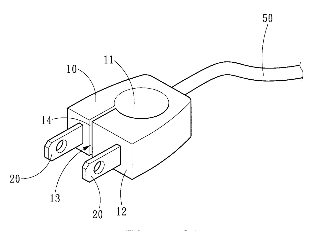
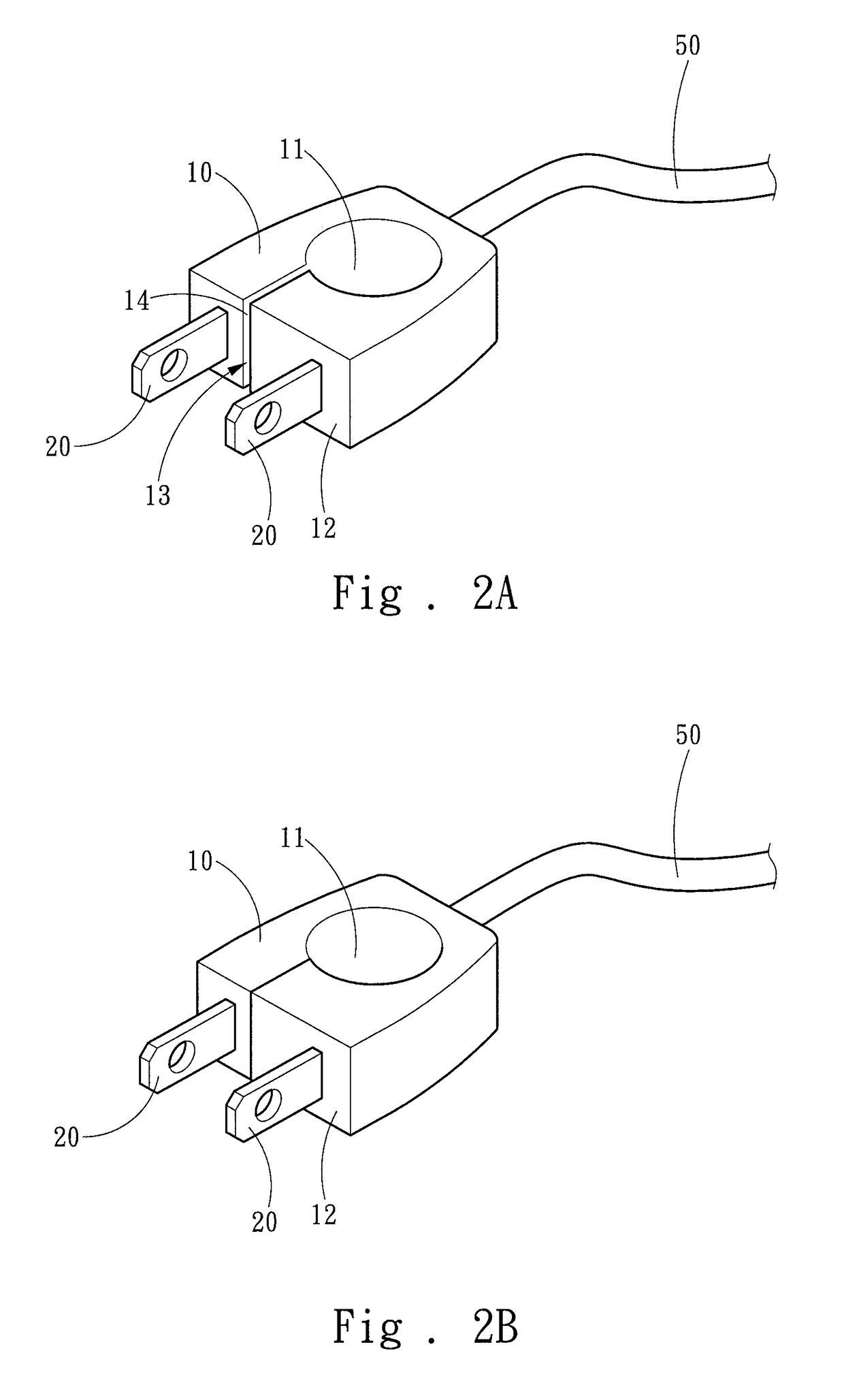
[0018]Referring to FIG. 2A and FIG. 2B, the present invention provides an electrical appliance plug structure, which includes a body 10 and two metal pins 20. The body 10 includes a through hole 11, an installation operating surface 12, a gap 13 in communication with the through hole 11 and the installation operating surface 12, and two contact surfaces 14 adjacent to the gap 13 and corresponding to each other. The two metal pins 20 are disposed on the installation operating surface 12 and are respectively located at two sides of the gap 13. Further, the body 10 includes a pressing position that causes the two contact surfaces 14 to be in mutual contact (shown in FIG. 2B), and a loosened position that causes the two contact surfaces 14 to be away from each other (shown in FIG. 2A).

[0019]Copper plates in a socket may become dislocated from an original position when the socket ...


PUM


Abstract

An electrical appliance plug structure includes a body and two metal pins. The body includes a through hole, an installation operating surface, a gap in communication with the through hole and the installation operating surface, and two contact surfaces adjacent to the gap and corresponding to each other. The body has a pressing position that causes the two contact surfaces to be in mutual contact and a loosened position that causes the two contact surfaces to be away from each other. The two metal pins are disposed at the installation operation surface and are respectively located at two sides of the gap. When the two metal pins are inserted into a socket, the body is located at the loosened position to outwardly abut against copper plates in the socket to conduct current. After use, a finger is inserted into the through hole to easily remove the plug.

Description

FIELD OF THE INVENTION[0001]The present invention relates to a plug, and particularly to an electrical appliance plug structure.BACKGROUND OF THE INVENTION[0002]A plug is a mobile connector that may be inserted into a corresponding socket to connect an electrical appliance to a power source and cause the electrical appliance become operable. Referring to FIG. 1A showing a connection of a common plug and socket, a plug 1 includes a body 2 and two metal pins 3. By inserting the plug 1 into a socket 4, copper plates 5 in the socket 4 may clamp the two metal pins 3 to stabilize the plug 1 and cause the two metal pins 3 to be electrically connected to the copper plates 5, so as to provide power.[0003]However, when the socket 4 is used over an extended period of time or improperly disposed, as shown in FIG. 1B, the copper plates 5 therein may age and become loose. At this point, the copper plates 5 may fail to securely clamp the two metal pins 3, in a way that not only the plug 1 likely b...

Claims


Application Information

Patent Timeline
Patent Type & Authority Applications(United States)
IPC IPC(8): H01R24/30H01R13/08
CPCH01R24/30H01R2103/00H01R13/08H01R13/6335
Inventor YU, CHUNG-HSIN
Owner YU CHUNG HSIN
Why Eureka
Try Eureka