Control Circuit and Control Method of Switching Power Supply

Active Publication Date: 2018-10-04
WUXI CHIPOWN MICROELECTRONICS
View PDF0 Cites 13 Cited by
  • Summary
  • Abstract
  • Description
  • Claims
  • Application Information

AI Technical Summary

Benefits of technology

[0023]1. The switching power supply of the present disclosure outputs constant current in the continuous working mode and/or in the quasi-resonant working mode, without increasing the quantity of the pins of the control circuit and the elements of the power system, nor the design cost thereof. The present disclosure regulates the scaling parameters of the constant current control circuit through detecting the working mode and/or the resonant period, so as to compensate the difference of the constant currents output between different working modes; and regulates the sampling point of the current at the primary side through detecting the off delay of the power switch and the static error of the current sampled at the primary side, so as to compensate the difference of the constant currents output under different input voltages. Additionally, at the initial stage of starting, the detection results to the primary side information is shielded, and separated starting parameters are set, thereby charging the output capacitor more rapidly, establishing the output voltage more quickly and starting the switching power supply more quickly. Through control and compensation, the precision of the constant current output of the switching power supply is enhanced and the switching power supply is started-up more quickly.
[0024]2. Through detecting the working mode and/or the resonant cycle, the present disclosure regulates the scaling parameters of the constant current control circuit, so as to compensate the difference of the constant currents output between different working modes; through detecting the off delay of the power switch and the static error of the sampled current at the primary side, the present di

Problems solved by technology

One of the obvious defects of the traditional constant current output control method above is that, when the flyback switching power supply works in a Continuous Conduction Mode (CCM), namely, when VCS_O is not equal to zero, the constant current control method becomes invalid.
What's more, even when the flyback switching power supply works in the DCM, the constant current control method requires the ratio of TP to TD strictly constant, which is not compatible with the valley switching (QR) mode in the DCM.
Therefore, the power supply adopting the constant current output control method above has the defect of low efficiency; what's more, the design of th

Method used


Image

  • Control Circuit and Control Method of Switching Power Supply
  • Control Circuit and Control Method of Switching Power Supply
  • Control Circuit and Control Method of Switching Power Supply

Examples


Example

[0041]For a better understanding of the technical features, the objective and the technical effect of the present disclosure, embodiments of the technical scheme of the present invention will be described in more details with reference to the accompanying figures.

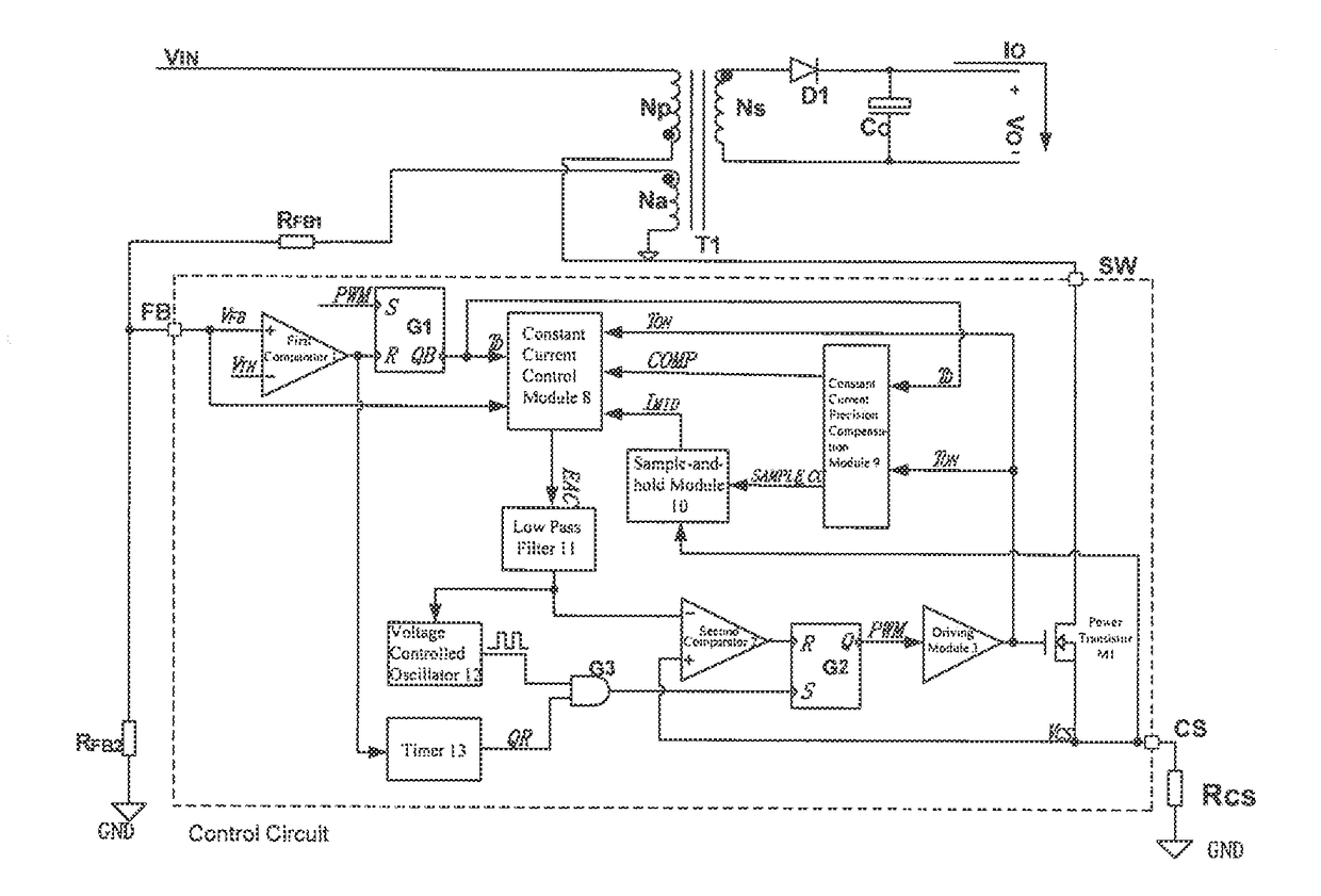
[0042]The control circuit and the power supply system of the switching power supply are shown in FIG. 4. The power supply system includes a transformer T1, an output diode D1, an output capacitor CO, a resistor RFB1, a resistor RFB2, a resistor RCS and a control circuit. A pin FB of the control circuit is electrically connected with the resistor RFB1 and the resistor RFB2 respectively; a pin CS of the control circuit is electrically connected with the resistor RCS; a pin SW of the control circuit is electrically connected with a primary side Np of the transformer.

[0043]The control circuit includes a first comparator 1, a first RS flip-latch G1, a constant current control module 8, a constant current precision compensation m...


PUM


Abstract

What disclosed are a control circuit and a control method of a switching power supply, according to feedback signals on a pin FB and a pin CS, a constant current control module generates and outputs a control signal to control an output current of the switching power supply, thereby regulating duty cycle of a first transistor adaptively and controlling an output current Io of a power supply system to be constant; according to the feedback signals on the pin FB and on the pin CS, a constant current precision compensation module adaptively regulates circuit parameters of the constant current control module and a sample-and-hold module, preventing precision of constant current output from being influenced by change of a working mode and/or by variation of input conditions; when an output voltage changes, QR mode keeps unchanged or depth of a CCM keeps approximately constant.

Description

CROSS REFERENCE TO RELATED APPLICATIONS[0001]This application claims the benefit of the priority of Chinese Patent Application No. 201710191750.5, filed on Mar. 28, 2017, entitled “Control Circuit and Control Method of Switching Power Supply”, the entire contents of which are incorporated herein by reference.TECHNICAL FIELD[0002]The present disclosure relates to improvements on a control circuit and a control method of a switching power supply, is applied in power management integrated circuit systems, and belongs to the technical field of power semiconductor.BACKGROUND OF THE INVENTION[0003]The output current of the flyback switching power supply is denoted as:IO=NPNS×IPRI_PK+IPRI_O2×TDTP,wherein,NPNSis the turns ratio of the primary side to the secondary side; IPRI_PK is the current peak value of the primary side during magnetization of the transformer; IPRI_O is the initial current value of the primary side during magnetization of the transformer; TD is the demagnetization time o...

Claims


Application Information

Patent Timeline
IPC IPC(8): H02M1/08H02M3/335
CPCH02M1/08H02M2001/0003H02M3/33523H02M3/33507H02M1/0003
Inventor LI, HAISONGZHAO, CHANGSHENLIU, WENLIANGYI, YANGBOZHOU, BIAOZHANG, TAORUI, HUAZHENG
Owner WUXI CHIPOWN MICROELECTRONICS
Why Eureka
Try Eureka