
Mounting Clamp For An Illuminated Surgical Retractor System

a technology of mounting clamps and retractors, which is applied in the field of illumination retractor systems, can solve the problems of inconvenient and potentially dangerous delay, the entire retractor system must be replaced, and the versatility of most such systems is not very good, so as to achieve quick, convenient and reliable secureness.

Active Publication Date: 2018-10-18
SUNOPTIC TECH
View PDF2 Cites 0 Cited by
  • Summary
  • Abstract
  • Description
  • Claims
  • Application Information

AI Technical Summary

Benefits of technology

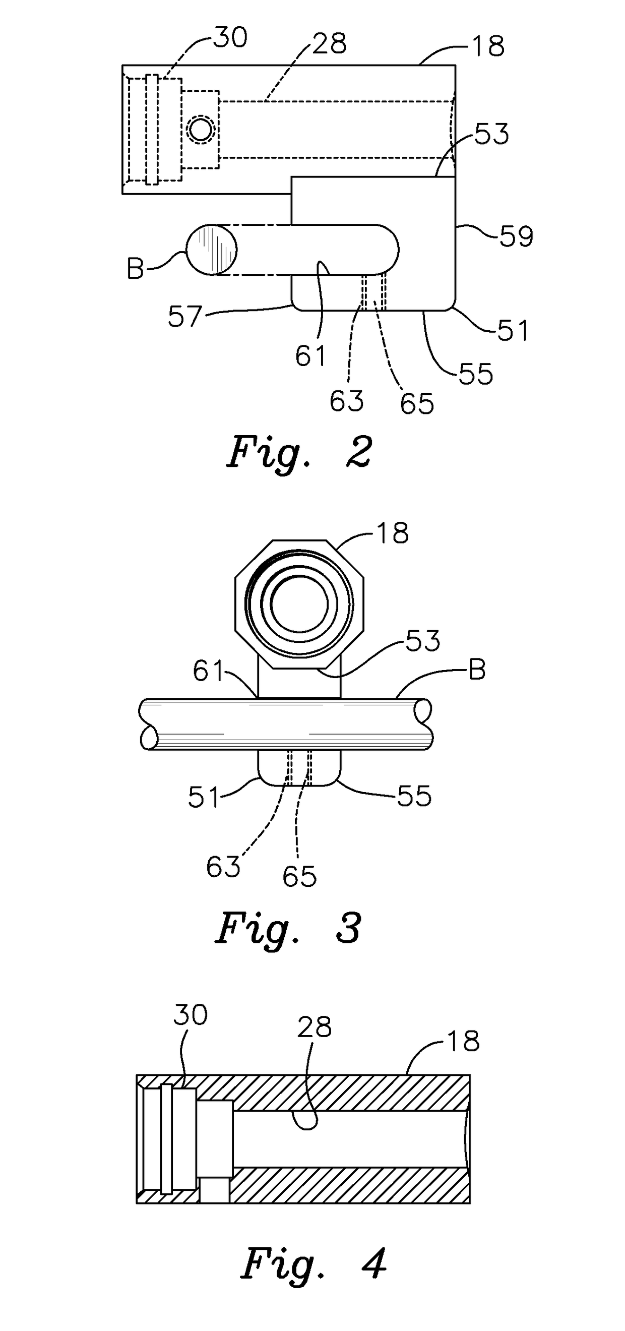
The present invention provides an illuminated surgical retractor system that can be quickly and securely attached to a surgical table using a mounting clamp. The clamp allows for easy adjustment and positioning of the retractor system, so that it can be used more effectively during surgery and without the need for manual holding by a physician. The clamp helps to free up the physician's hands to participate more effectively in the procedure. In a preferred embodiment, the clamp includes a receptacle for engaging the elongate structural component attached to the table, such as a slide bar, and a set screw assembly for securely placing the retractor system in a selected position.

Problems solved by technology

Most such systems are not very versatile.
The hospital or other surgical facility must therefore maintain a large number of differently sized and configured retractor systems, which can be quite costly.
As a result, if a single one of these components fails, the entire retractor system must be replaced.
This is not only expensive, it can also cause an inconvenient and potentially dangerous delay during a time sensitive surgical procedure.
Conventional illuminated retractors can also be awkward to manipulate and difficult to properly position and hold securely in place so that optimum surgical lighting is provided.

Method used


Image

  • Mounting Clamp For An Illuminated Surgical Retractor System
  • Mounting Clamp For An Illuminated Surgical Retractor System
  • Mounting Clamp For An Illuminated Surgical Retractor System

Examples


Embodiment Construction

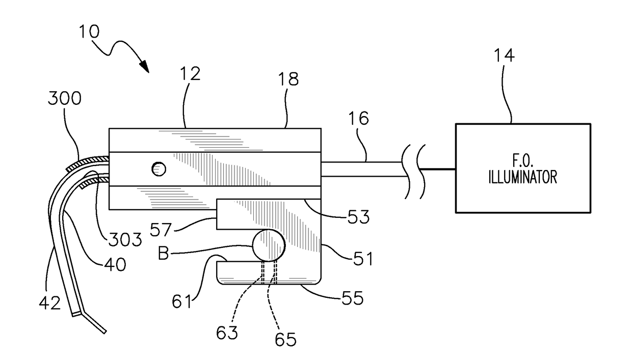
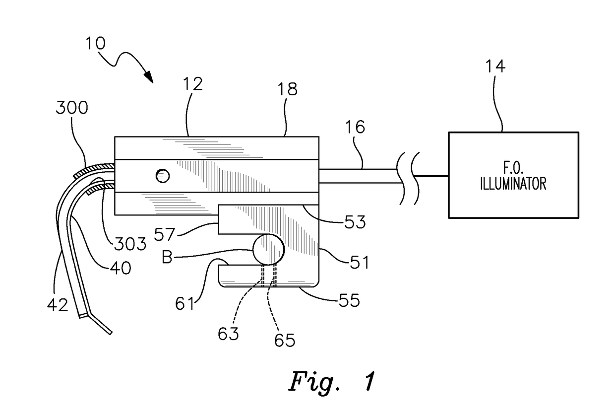
[0019]There is shown in FIG. 1 an illuminated surgical retractor system 10, which is intended for use during surgical and medical procedures. For example, system 10 may be used effectively for various types of plastic surgery including but not limited to breast augmentation. The system is also extremely effective for use in virtually all types of thoracic surgery involving the chest or abdomen wherein the edges of a surgical incision must be separated and / or tissue, muscles and internal organs must be constrained and the surgical site illuminated. It should be understood that the specific medical and surgical applications for which system 10 may be used are not a limitation of this invention.

[0020]Illuminated retractor system 10 includes a retractor apparatus 12 that is interconnected to a standard fiberoptic illuminator 14 by a fiberoptic cable 16. Various types of fiberoptic illuminators, which are either conventional or to be developed may be employed within the scope of this inv...


PUM


Abstract

A mounting clamp is disclosed for an illuminated surgical retractor system having a handle that supports an illuminated surgical retractor blade. The mounting clamp is attached to and depends from the handle. The mounting clamp includes a receptacle for receiving a slide bar or other fixed component of an operating room table. The clamp further includes a fastener that is selectively tightened to secure the retractor assembly to the fixed component of the table. The fastener is selectively loosened to disengage the retractor assembly from the fixed component of the table.

Description

RELATED APPLICATION[0001]This application claims the benefit of U.S. Provisional Patent Application Ser. No. 62 / 485,530 filed Apr. 14, 2017.FIELD OF THE INVENTION[0002]This invention relates to an illuminated retractor system for use in medical and surgical procedures. More particularly, the invention relates to a mounting clamp for releasably attaching the retractor system to a slide bar of an operating table at a selected position along the slide bar.BACKGROUND OF THE INVENTION[0003]Surgical retractors are commonly used by surgeons to separate the edges of a surgical incision or wound. Such instruments are also utilized to restrain the organs and tissues of a patient undergoing surgery so that body parts under the surgical incision may be more readily accessed. Most retractors employ one or more curved, hooked or angled steel blades attached to a handle that is manipulated during surgery by the surgeon or other medical personnel.[0004]Recently, surgical retractors have been improv...

Claims


Application Information

Patent Timeline
Patent Type & Authority Applications(United States)
IPC IPC(8): A61B17/02A61B1/06A61B90/30
CPCA61B17/0206A61B1/0615A61B90/30A61B17/0218A61B1/07A61B17/02A61B2090/306A61B1/32
Inventor DAVIS, JAMES M.MARSH, KIM A.
Owner SUNOPTIC TECH
Learn More