Variable Radius Sanding Block

Active Publication Date: 2018-10-25
ROUZBEH SEYED BABAK +1
View PDF0 Cites 0 Cited by
  • Summary
  • Abstract
  • Description
  • Claims
  • Application Information

AI Technical Summary

Benefits of technology

[0009]An additional object of the present invention is for radius patches of differing size to have correspondingly different colors in order to be more easily recognizable.
[0010]Another o

Problems solved by technology

For this reason, multiple sanding blocks in many wood

Method used


Image

  • Variable Radius Sanding Block
  • Variable Radius Sanding Block
  • Variable Radius Sanding Block

Examples


Example

[0020]Reference is made herein to the attached drawings. Like reference numerals are used throughout the drawings to depict like or similar elements of the variable radius sanding block. The figures are intended for representative purposes only and should not be considered to be limiting in any respect.

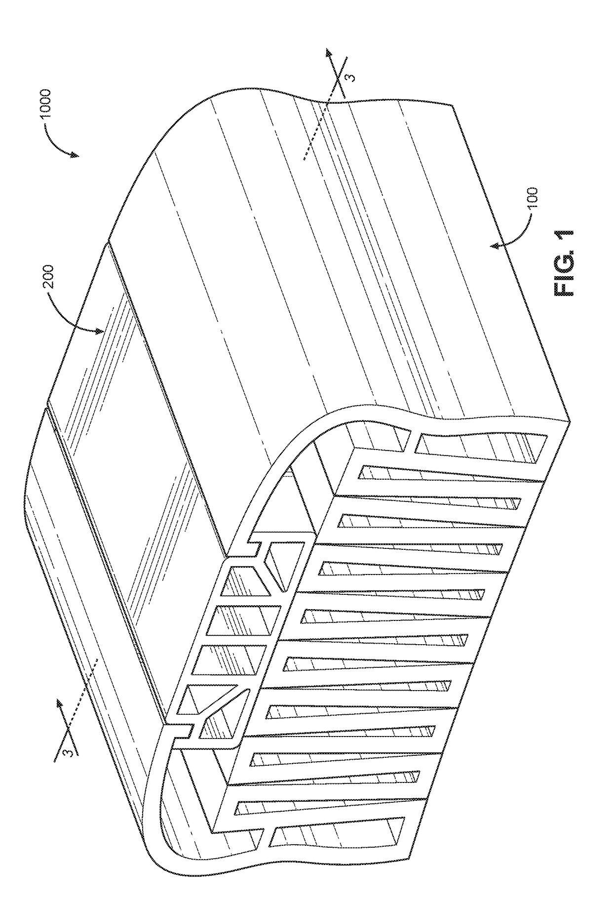
[0021]Referring now to FIG. 1, there is shown a perspective view of an assembled variable radius sanding block. The variable radius sanding block 1000 comprises a base member 100 and a plurality of variably sized radius patches 200. In the illustrated embodiment, assembly of the variable radius sanding block requires insertion of one of the radius patches 200 into the base member 100. In the illustrated embodiment, both the base member 100 and the radius patch 200 are made of an extruded plastic, such that the base member 100 is flexible and can be easily manipulated while the radius patch 200 is rigid and resistant to manipulation.

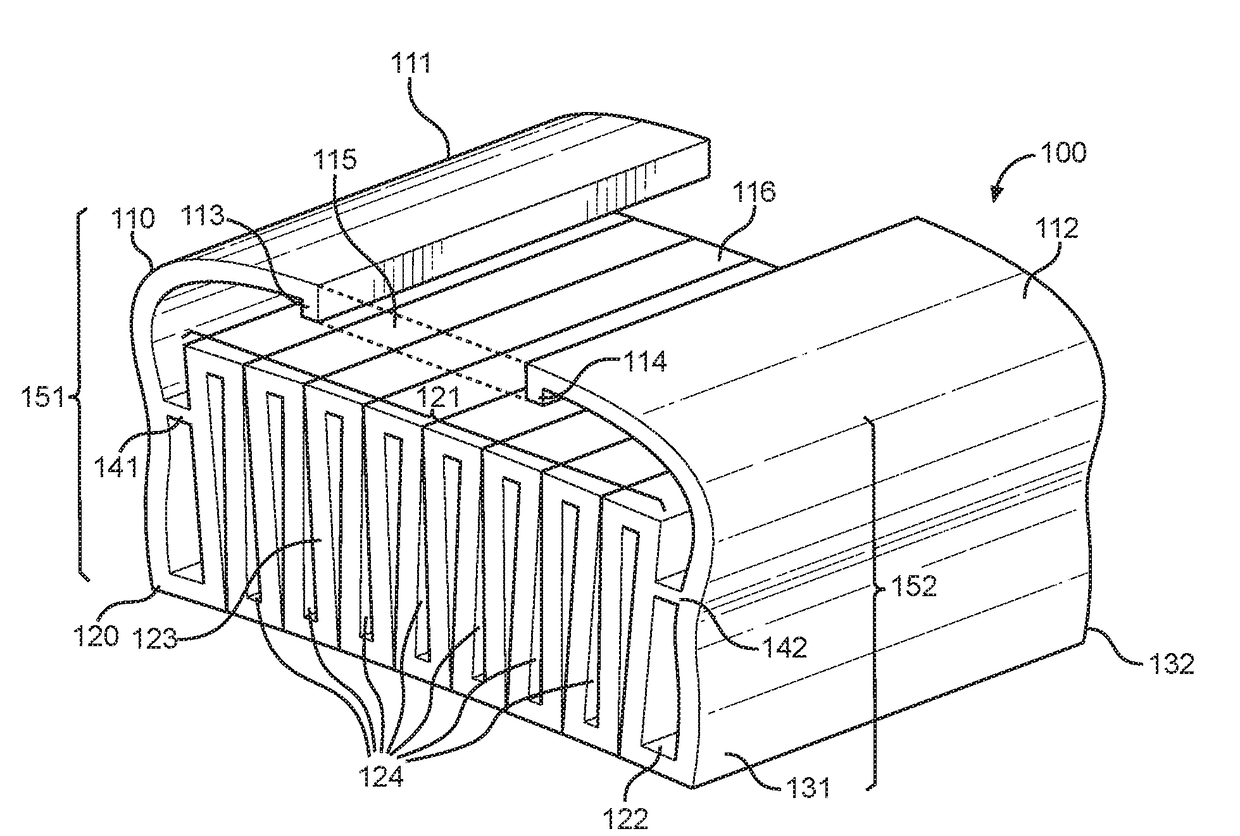
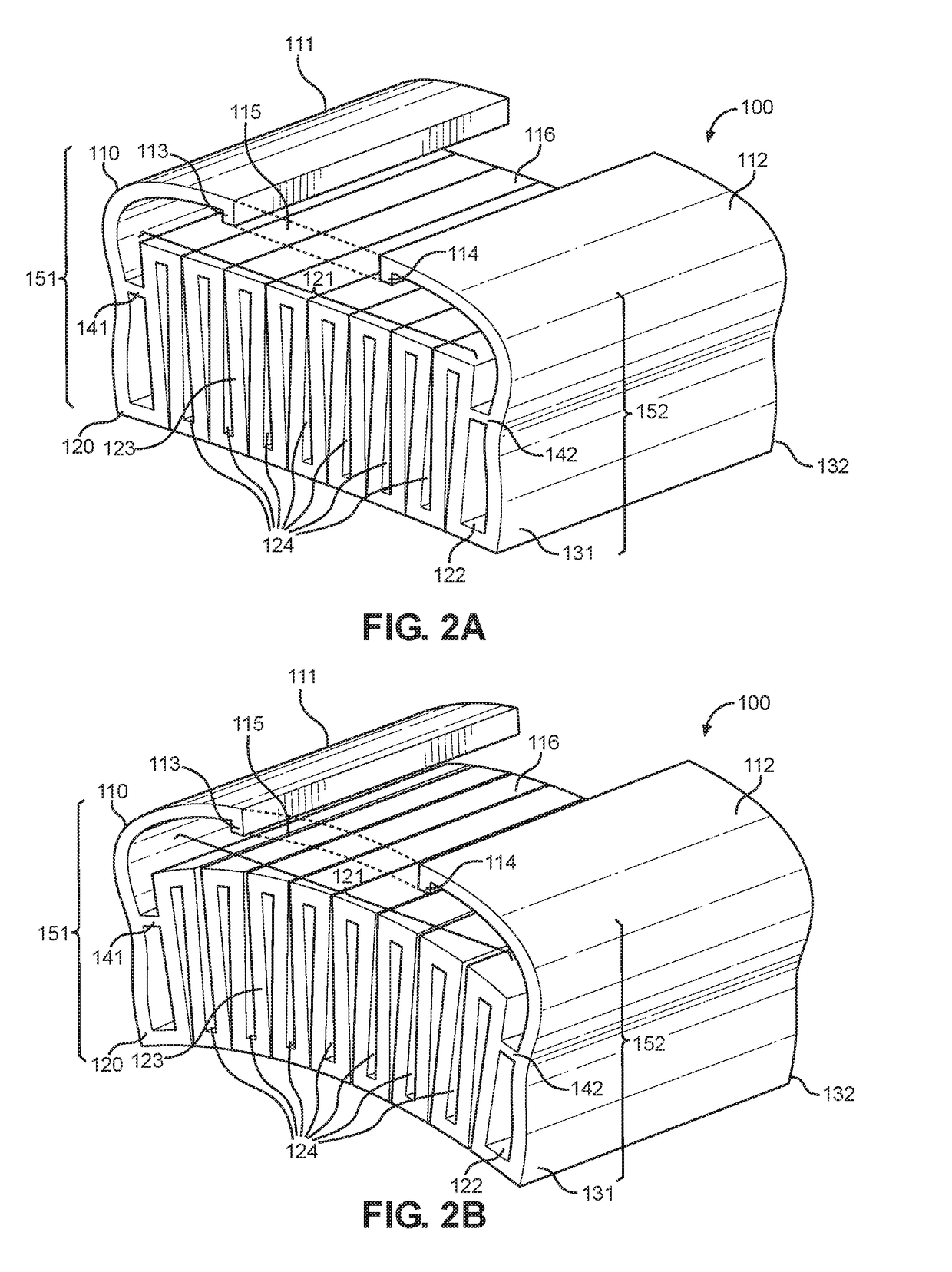
[0022]Referring now to FIGS. 2A and 2B there is shown...


PUM


Abstract

A variable radius sanding block for sanding curved surfaces. The variable radius sanding block includes a base member and a plurality of variably sized radius patches. The base member is sized and proportioned to allow radius patches of varying size to be inserted, such that each of the radius patches will change the curvature of the sanding block upon insertion. The base member also having a folded flexible internal structure and a pair of flexible arms that facilitate insertion of radius patches of varying size. The radius patch includes a pair of grooves that receive the flexible arms of the base member and secure the base member to the radius patch.

Description

CROSS REFERENCE TO RELATED APPLICATION[0001]This application claims the benefit of U.S. Provisional Application No. 62 / 489,819 filed on Apr. 25, 2017. The above identified patent application is herein incorporated by reference in its entirety to provide continuity of disclosure.BACKGROUND OF THE INVENTION[0002]The present invention relates to the sanding of wood, musical instruments, and other rounded surfaces.[0003]Sanding blocks conventionally are provided having a fixed curvature that is only intended to be used to sand objects of a corresponding curvature. In order for most wood workshops to be able to sand a wide range of surfaces they have to maintain several sanding blocks, where each one has a different curvature. For this reason, multiple sanding blocks in many wood workshops tend to take up substantial amounts of space. In order to address these concerns, the present invention provides a sanding block having a curved surface whose curvature can be changed to match the curv...

Claims


Application Information

Patent Timeline
IPC IPC(8): B24B23/04B24B5/35B24B5/50
CPCB24B23/046B24B5/35B24B5/50B24D15/04
Inventor ROUZBEH, SEYED BABAKROUZMEH, SEYEDEHSHAGHAYEGH
Owner ROUZBEH SEYED BABAK
Why Eureka
Try Eureka