Self-Igniting Assembly

Inactive Publication Date: 2018-11-01
REAM SHAWN ALEXANDER
View PDF0 Cites 1 Cited by
  • Summary
  • Abstract
  • Description
  • Claims
  • Application Information

AI Technical Summary

Benefits of technology

[0014]In an aspect of the invention, the assembly also has an end member which fittingly engages the ignition assembly. The end member is comprised of a cavity dimensioned

Problems solved by technology

While effective, they rely on an adequate supply of butane as a fuel source and are therefore not a permanent i

Method used


Image

  • Self-Igniting Assembly
  • Self-Igniting Assembly
  • Self-Igniting Assembly

Examples


Embodiment Construction

[0037]The specific details of the single embodiment or variety of embodiments described herein are set forth in this application. Any specific details of the embodiments are used for demonstration purposes only and no unnecessary limitation or inferences are to be understood therefrom.

[0038]Any reference to “invention” within this document is a reference to an embodiment of a family of inventions, with no single embodiment including features that are necessarily included in all embodiments, unless otherwise stated. Furthermore, although there may be references to “advantage's” provided by some embodiments, other embodiments may not include those same advantages, or may include different advantages. Any advantages described herein are not to be construed as limiting to any of the claims.

[0039]Before describing in detail exemplary embodiments, it is noted that the embodiments reside primarily in combinations of components related to the system. Accordingly, the system and method compo...


PUM


Abstract

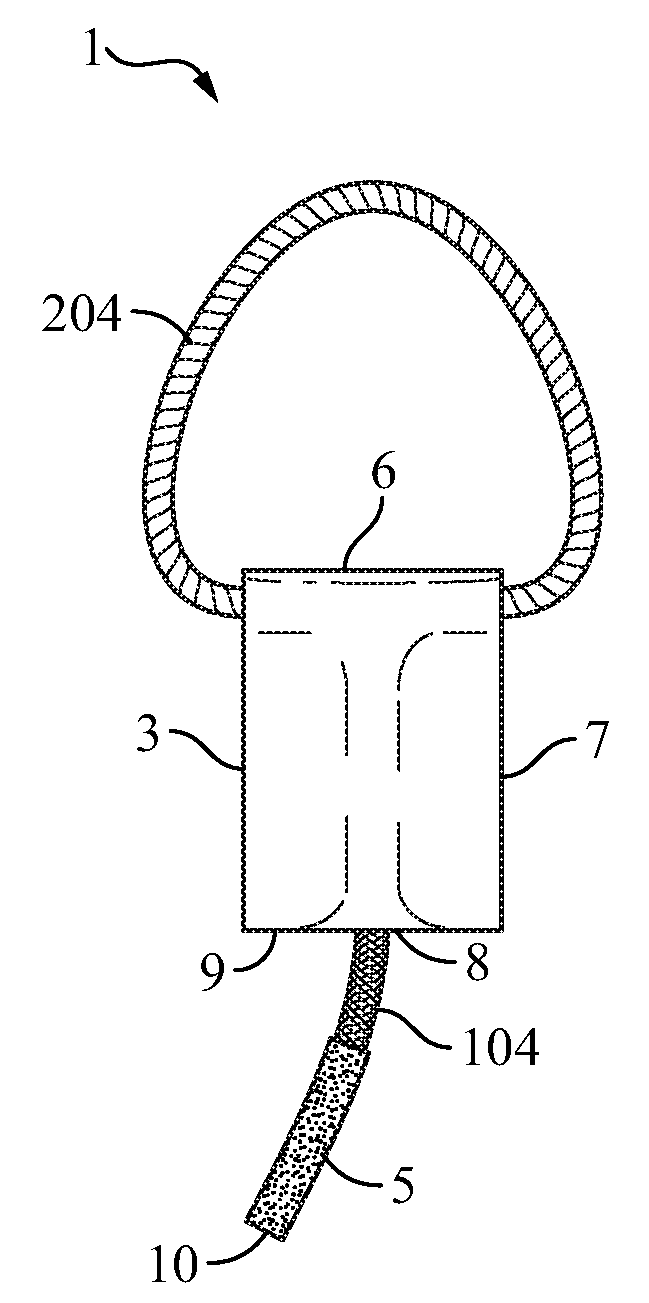
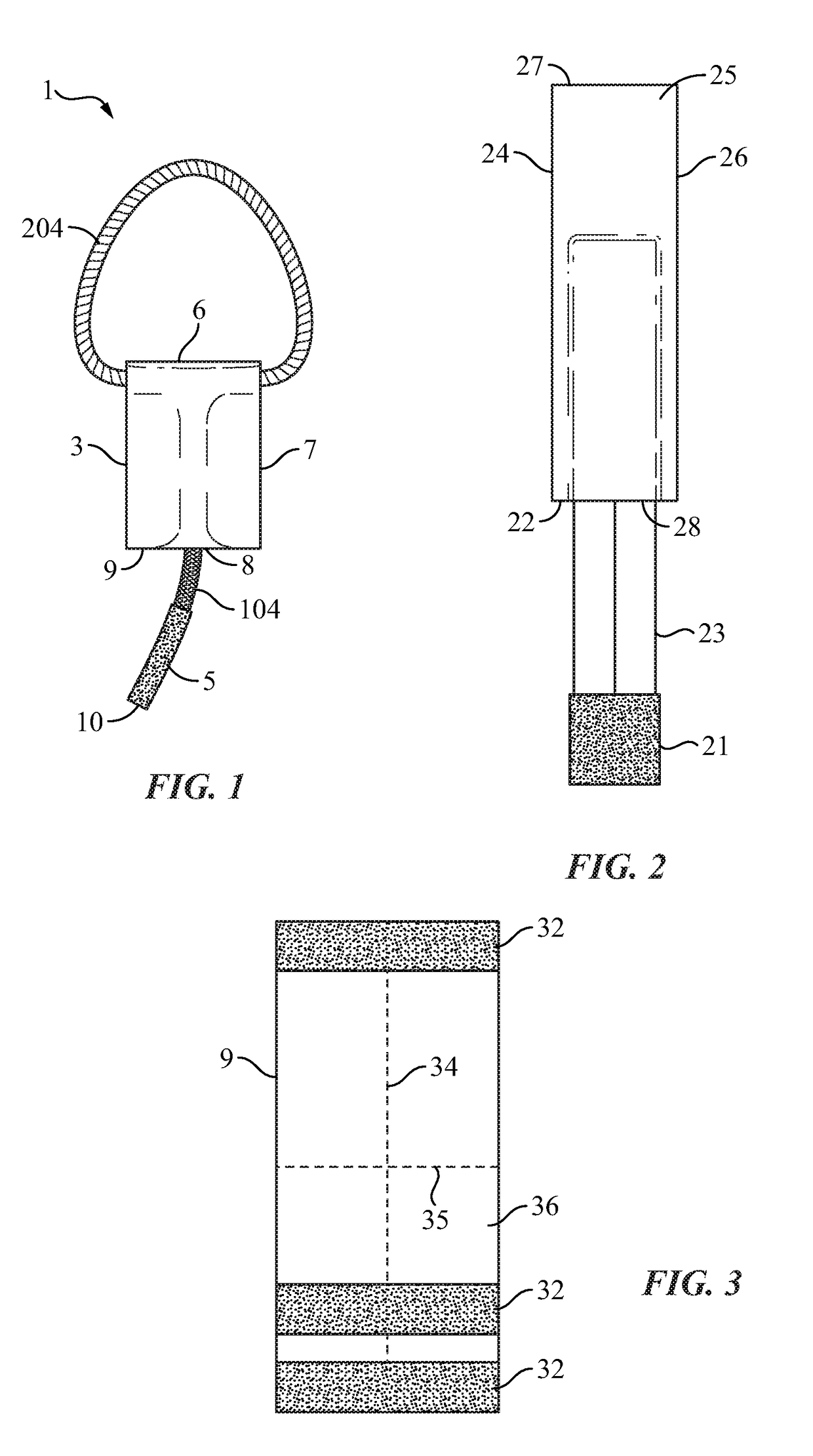
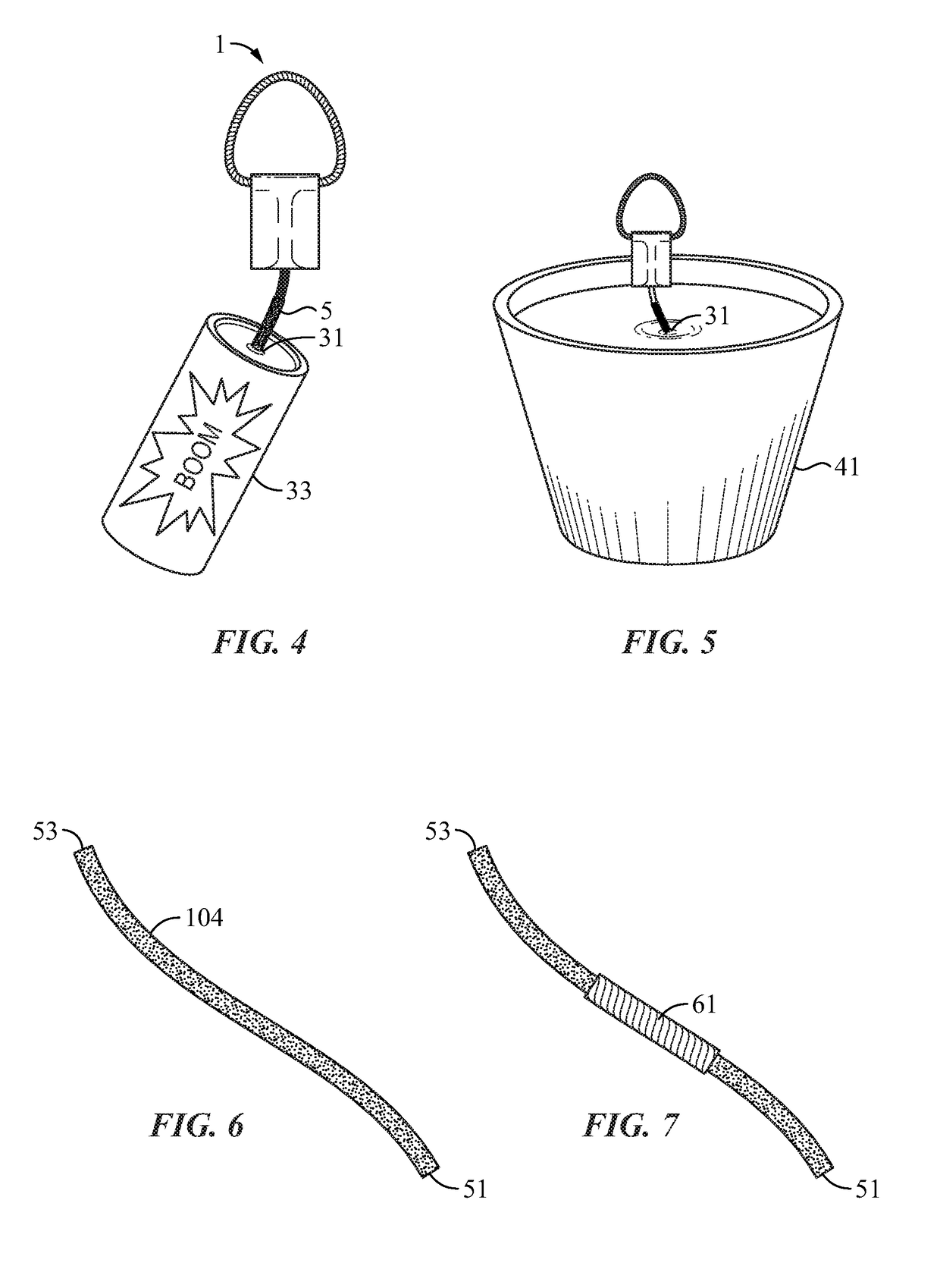
Embodiments are described for a self-igniting assembly having a main portion with a match-like component affixed thereto. A flammable member such as a wick or match-like member is in communication with the match-like component. A handle permits the user to grip the main portion and tug the main portion to impart friction and a chemical reaction between the match-like component to ignite the flammable member. This assembly may be provided with a number of ignitable device such as logs, fire starters, fireworks, or candles.

Description

CROSS REFERENCE TO RELATED APPLICATIONS[0001]This application claims priority to U.S. Provisional Application 62 / 492,483 filed May 1, 2017 which is hereby incorporated by reference.FIELD[0002]The present invention relates to fire starting implements which may be used to ignite a multitude of devices.BACKGROUND[0003]Many devices and processes exist which require a fire starter, in one form or another, to serve as a primary ignitor. Some examples may include candles, fireworks, barbeque and campfire starters, and fire logs for home use. These devices are typically provided to the consumer without a means for igniting the product. In the current arts, the most common options are matches, lighters, and torches. While many of these items were commonplace in the past, the reduction in the prevalence of smoking has left many homes without the ever-present need for a lighter.[0004]Butane lighters may perhaps be the most common source of ignition for users in the developed world. While effec...

Claims


Application Information

Patent Timeline
IPC IPC(8): C10L11/04C06F5/00C06C5/06
CPCC06C5/06C10L11/04C06F5/00C10L5/365C10L5/368C10L2230/06
Inventor REAM, SHAWN ALEXANDER
Owner REAM SHAWN ALEXANDER
Why Eureka
Try Eureka