Assembly for an electronic locking system and electronic locking system comprising the assembly

Active Publication Date: 2018-11-15
ASSA ABLOY AB
View PDF2 Cites 5 Cited by
  • Summary
  • Abstract
  • Description
  • Claims
  • Application Information

AI Technical Summary

Benefits of technology

The present disclosure is about an electronic locking system that has a simple and reliable design. The system includes engaging members that have roller bearings that allow them to rotate smoothly with the lock. The transmission arrangement includes a flywheel and a freewheel that work together to prevent peaks in rotational speed. This results in a more reliable and compact assembly for the locking system.

Problems solved by technology

Drawbacks of the device in US 2014 / 0225375 A1 include a bulky structural design and that the device is complicated to install in a door.

Method used


Image

  • Assembly for an electronic locking system and electronic locking system comprising the assembly
  • Assembly for an electronic locking system and electronic locking system comprising the assembly
  • Assembly for an electronic locking system and electronic locking system comprising the assembly

Examples


Embodiment Construction

[0061]The invention will now be described more fully hereinafter with reference to the accompanying drawings, in which certain embodiments of the invention are shown. This invention may, however, be embodied in many different forms and should not be construed as limited to the embodiments set forth herein; rather, these embodiments are provided by way of example so that this disclosure will be thorough and complete, and will fully convey the scope of the invention to those skilled in the art. Like numbers refer to like elements throughout the description.

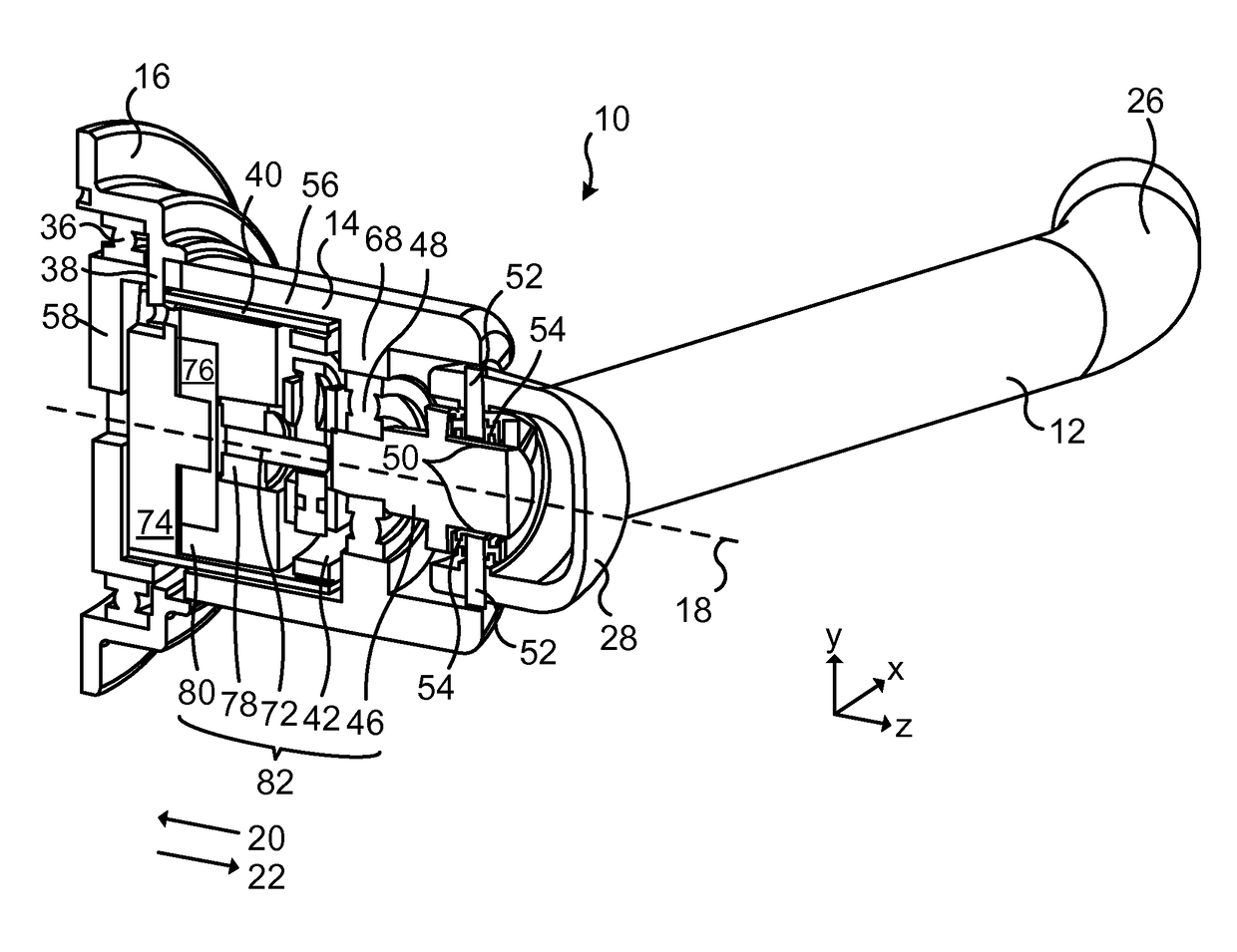
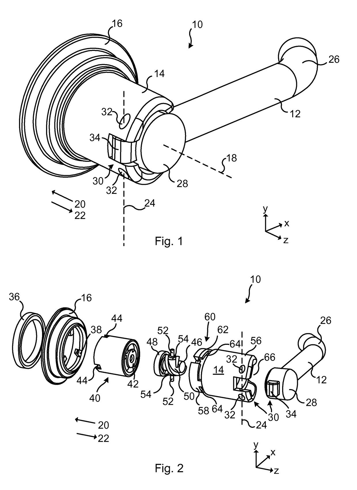
[0062]FIG. 1 schematically represents a perspective view of an assembly 10 for an electronic locking system. The assembly 10 comprises an actuating element 12 and a housing 14. In FIG. 1, the actuating element 12 is rotatably arranged with respect to a base member 16 for rotation about a first axis 18. The assembly 10 in FIG. 1 also comprises the base member 16. Arrow 20 indicates a distal or forward direction and arrow 22 indicates...


PUM


Abstract

Assembly (10) for an electronic locking system (84), the assembly (10) comprising an actuating element (12) rotatably arrangable with respect to a base member (16) for rotation about a first axis (18) and rotatably arranged about a second axis (24) substantially perpendicular to the first axis (18), an electric generator (74) comprising a rotor (76), and a transmission arrangement (82) configured to transmit a rotational actuation of the actuating element (12) about the second axis (24) into a rotation of the rotor (76) of the electric generator (74) to generate electric energy.

Description

TECHNICAL FIELD[0001]The present disclosure generally relates to an assembly for an electronic locking system. In particular, an assembly for an electronic locking system and an electronic locking system comprising the assembly are provided.BACKGROUND[0002]Various types of electronic locking systems are known. Instead of utilizing a purely mechanical lock, some locking systems include an electronic drive of a lock member (e.g. a lock bolt) to unlock, for example, a door to give access to the area behind the door.[0003]Furthermore, instead of utilizing a traditional key to unlock the door, various types of electronic communication methods for authorizing a person to access the area behind the door are known. For example, a Radio Frequency Identification (RFID) system may be used where a reader of the RFID system is installed in the door and a tag is carried by or attached to an object to be identified.[0004]In order to power an electronic locking system, so called “self-powered” elec...

Claims


Application Information

Patent Timeline
IPC IPC(8): E05B1/00H02K7/18
CPCE05B1/003E05B1/0092H02K7/1853E05B2047/0062E05B7/00E05B2001/0076
Inventor COSTER, ANDERSSKARP, DANIELMCGOUGAN, ROBIN
Owner ASSA ABLOY AB
Why Eureka
Try Eureka