Laser scanning sensor

a laser scanning and sensor technology, applied in the field of laser scanning sensors, can solve problems such as inability to hold laser scanning sensors, and achieve the effect of remarkable flexibility in the setting of a detection area

Active Publication Date: 2018-11-15
OPTEX CO LTD
View PDF0 Cites 0 Cited by
  • Summary
  • Abstract
  • Description
  • Claims
  • Application Information

AI Technical Summary

Benefits of technology

[0017]The laser scanning sensor according to the present invention can be firmly installed on whichever of a ceiling surface and a wall surface and enables various installation patterns, thereby allowing remarkable flexibility in the setting of a detection area.

Problems solved by technology

Hence, for example, it is inappropriate to hold the laser scanning sensor by a flexible arm or something else.

Method used


Image

  • Laser scanning sensor
  • Laser scanning sensor
  • Laser scanning sensor

Examples


Embodiment Construction

[0027]Hereinafter, embodiments of the present invention are described with reference to the drawings.

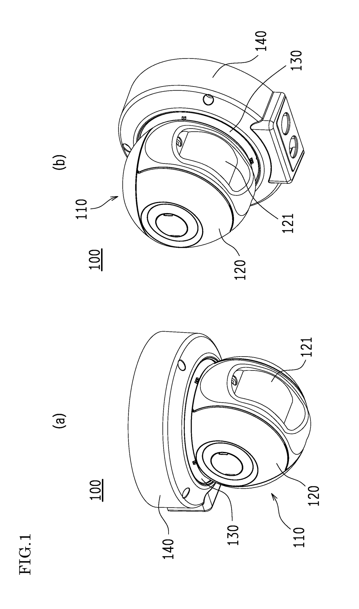
[0028]FIG. 1(a) is an external view of a laser scanning sensor 100 to be mounted on a ceiling surface, in an embodiment of the present invention. FIG. 1(b) is an external view of the laser scanning sensor 100 to be mounted on a wall surface.

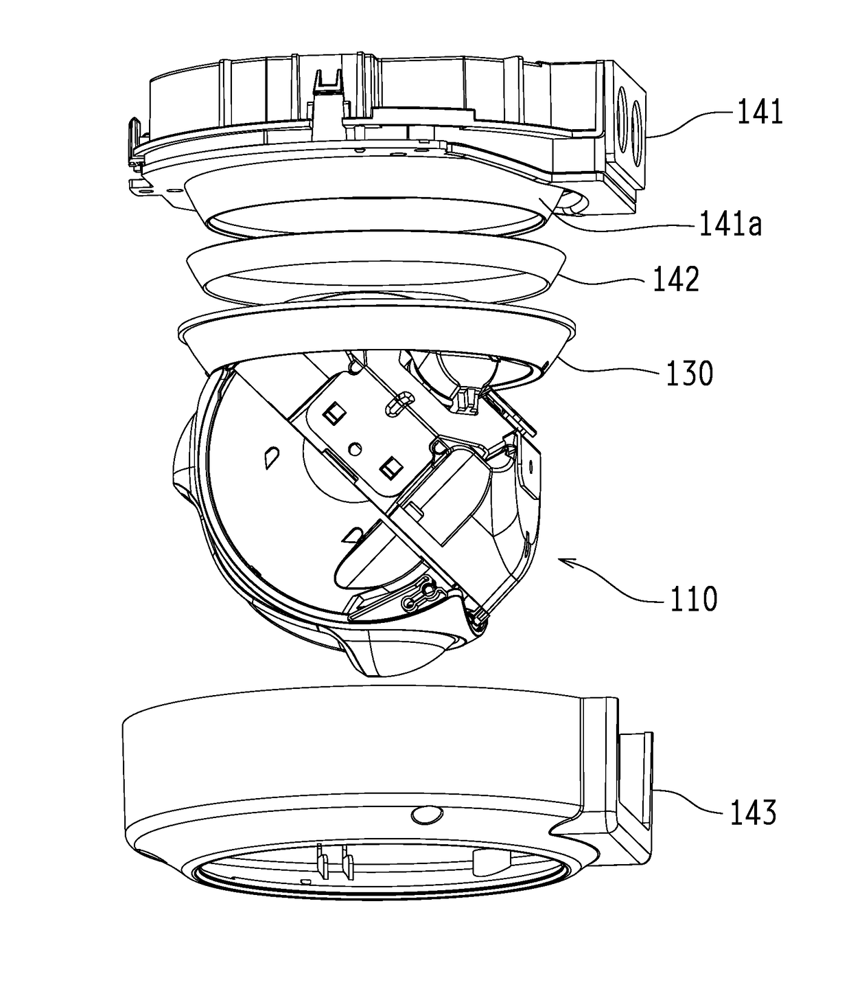
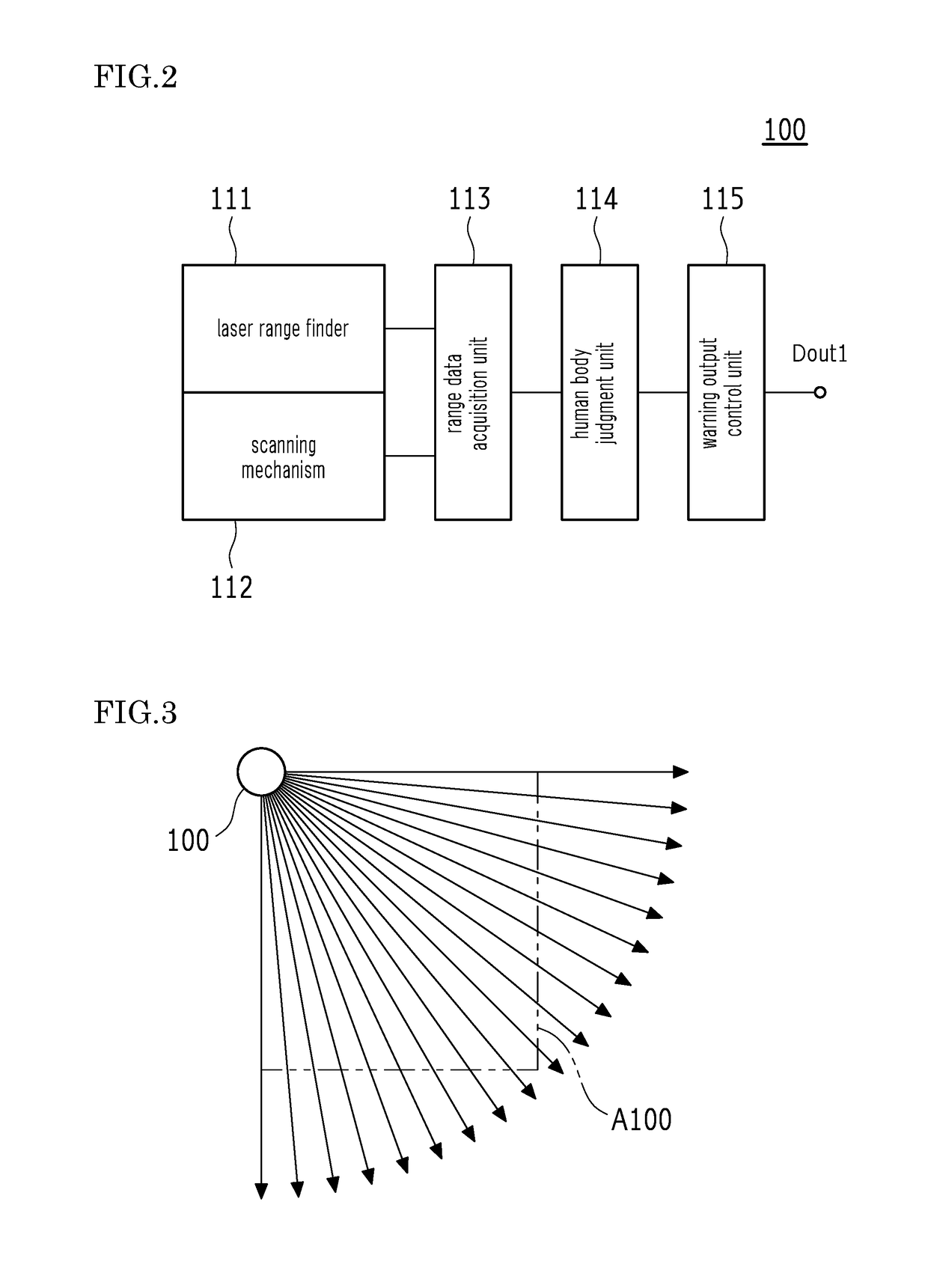
[0029]As shown in FIGS. 1(a) and 1(b), the laser scanning sensor 100 has a head part 110 which includes a round housing 120 and a laser window 121 provided in the housing 120, a base part 140 to be mounted on an installation surface such as a ceiling surface or a wall surface, and a joint part 130 for joining the head part 110 and the base part 140.

[0030]For example, the laser scanning sensor 100 may be mounted on a ceiling surface as shown in FIG. 1(a) and may form a detection area A100 (to be described later with reference to FIG. 3) below the ceiling surface. Alternatively, the laser scanning sensor 100 may be mounted on a wall surface as shown...


PUM


Abstract

A laser scanning sensor (100) includes: a head part (110) having a shape inscribed in a virtual cube, wherein the head part has a wiring hole (122) oriented to an intersection of three mutually orthogonal planes in the cube, and attachment portions (123a-123c) provided one each at inscribed points in the three planes, and wherein the head part is further configured to acquire range information in each measurement direction by containing a laser range finder (111) and a scanning mechanism (112) for changing a measurement direction by the laser range finder (111); a base part (140) configured to be mounted on an installation surface; and a joint part (130) configured to join any one of the attachment portions (123a-123c) in the head part (110) with the base part (140).

Description

TECHNICAL FIELD[0001]The present invention relates to a laser scanning sensor, for example, for detecting an intruder or the like on the building's premises, and particularly relates to a laser scanning sensor which can be installed on whichever of a ceiling surface and a wall surface and which allows greater flexibility in the setting of a detection area or in other respects.BACKGROUND ART[0002]A laser scanning sensor for detecting an intruder or the like on the building's premises has been proposed by conventional techniques (e.g. see PTL 1).[0003]According to a laser scanning sensor 100 disclosed in PTL 1, a detection area A100 is formed in a fixed direction with respect to a housing 101. In order to change the direction of forming the detection area A100, it is necessary to change the installation location and orientation of the housing101 in some manner (for example, by using a dedicated attachment member, or otherwise).[0004]As a precondition for precise range measurement, a l...

Claims


Application Information

Patent Timeline
Patent Type & Authority Applications(United States)
IPC IPC(8): G01S7/481G08B13/183G01S17/42G01S17/04
CPCG01S7/4817G01S7/4813G08B13/183G01S17/42G01S17/58G01S7/4808G01S17/04G08B13/189
Inventor KATSUMI, KEISUKE
Owner OPTEX CO LTD
Why Eureka
Try Eureka