Near-eye foveal display

a display and near-eye technology, applied in the field of display systems, can solve problems such as cumbersomeness and bulkiness, and achieve the effect of rapid frame rate and high resolution

Inactive Publication Date: 2018-11-15
SOLIDDD
View PDF1 Cites 4 Cited by
  • Summary
  • Abstract
  • Description
  • Claims
  • Application Information

AI Technical Summary

Benefits of technology

[0007]In accordance with the present invention, a method and system uses a plurality of light-emitting devices behind a plurality of light-directing beads or microlenses in relation to a user's eye. The device is called a foveal display because it focuses light directly and preci...

Problems solved by technology

The device replaces the typical optics in a ...

Method used


Image

  • Near-eye foveal display
  • Near-eye foveal display
  • Near-eye foveal display

Examples


Embodiment Construction

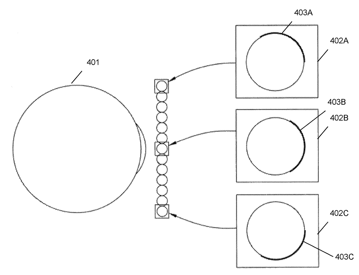
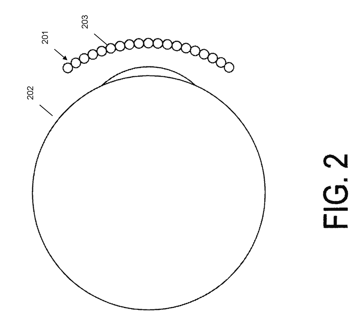
[0016]In accordance with the present invention, an embodiment provides a method and system of providing a high-resolution near-eye display. The system provides for a near-eye display without the large and cumbersome headsets found in conventional virtual reality headsets. The apparatus comprises a plurality of light-directing beads or microlenses, where the lenses are arranged in a pattern having a first dimension and a second dimension. The first dimension may include a horizontal dimension and the second dimension may include a vertical dimension, for example, as in a matrix or grid-like pattern. Alternatively, the pattern having the first dimension and a second dimension may not be in a grid-like pattern but may instead include a different pattern structure, for example, a brick-like pattern structure, an alternating pattern structure, or the like.

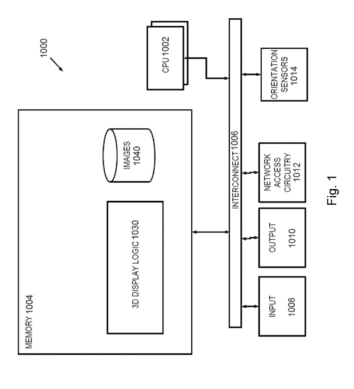
[0017]The apparatus may also include a display comprising a plurality of pixels, for example, a plurality of light emitting devices, a...


PUM


Abstract

An apparatus and system for a display screen for use in near-eye display devices. Small light emitting devices are placed behind a plurality of light-directing beads. The light emitting devices and light-directing beads for a display device and system placed in front of a user for near-eye display. This allows a user to experience near-eye display with greater resolution, wider field of view and faster frame rate. Other embodiments are described herein.

Description

FIELD OF THE INVENTION[0001]The present invention relates generally to display systems, and, more particularly, to display systems for near-eye displays such as virtual reality and augmented reality.BACKGROUND OF THE INVENTION[0002]Recently, there has been significant growth in the use and advancement of virtual reality, augmented reality, and similar near-eye products. Common virtual reality uses include video gaming, movies, amusement ride simulators, and the like. While the popularity is driven by entertainment, the products also serve functions in training and education. For example, virtual reality headsets may be used for flight simulation training, surgery simulation for physicians, technology in the traditional classroom to spark student interest in a subject, and the like.[0003]One method of producing a virtual reality simulation is the use of a headset. The headset contains a display with lenses placed between the eyes and display. The lenses serve to focus and reshape the...

Claims


Application Information

Patent Timeline
IPC IPC(8): G02B27/22G02B27/00G02B3/00G02B30/27
CPCG02B27/2214G02B3/0056G02B27/0093G02B2027/012G02B2027/0123G02B30/27
Inventor MULLER, RICHARD A.WEINSTOCK, NEAL
Owner SOLIDDD
Why Eureka
Try Eureka