
Smart pan for representation of physical space

a technology of physical space and intelligent pan, applied in the direction of image enhancement, image analysis, aircraft traffic control, etc., can solve the problem of complex air traffic control activity, achieve high resolution displays, reduce graphics processing requirements and energy consumption, and extend the user's field of awareness

Inactive Publication Date: 2017-04-20
FRENCH CIVIL AVIATION UNIVERSITY
View PDF0 Cites 8 Cited by
  • Summary
  • Abstract
  • Description
  • Claims
  • Application Information

AI Technical Summary

Benefits of technology

The patent describes a method that allows users to be alerted to objects outside their current field of view and shift their perspective to those objects. This approach can provide a smaller area to the user at any given time, reducing the need for high resolution displays and improving the user's ability to anticipate and remedy problems. In simple terms, this approach can improve safety and reduce costs by giving users a faster and more intuitive way to see and respond to external events.

Problems solved by technology

The activity of air traffic control is complex.

Method used


Image

  • Smart pan for representation of physical space
  • Smart pan for representation of physical space
  • Smart pan for representation of physical space

Examples


Embodiment Construction

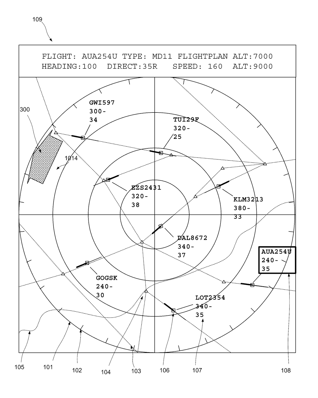
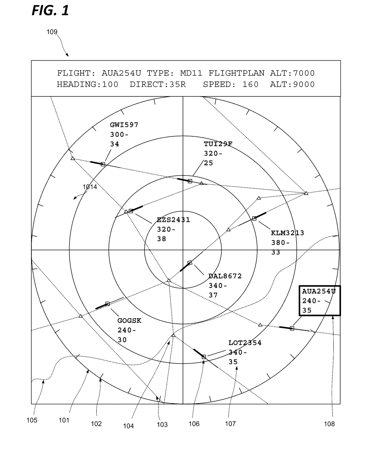
[0042]In many use scenarios relating to a computer generated graphical representation of a physical space, and in particular in the case of an air traffic controller monitoring a designated air space, a user's attention will be primarily attached to one particular area of the graphical representation, but for a variety of reasons will be called upon to temporarily shift the focus of their attention, and correspondingly the graphical representation, to another area. Other examples include navigation aids such as GPS navigation devices and software, in particular where integrated with a vehicle, targeting interfaces for military hardware, tactical mapping, status monitoring for large installations (industrial, public transport, utilities, communications, etc,), site monitoring, situation management for law enforcement and other civic bodies, and so on.

[0043]The user will often then wish to revert to the original area of attention, and require the graphical representation to be updated...


PUM


Abstract

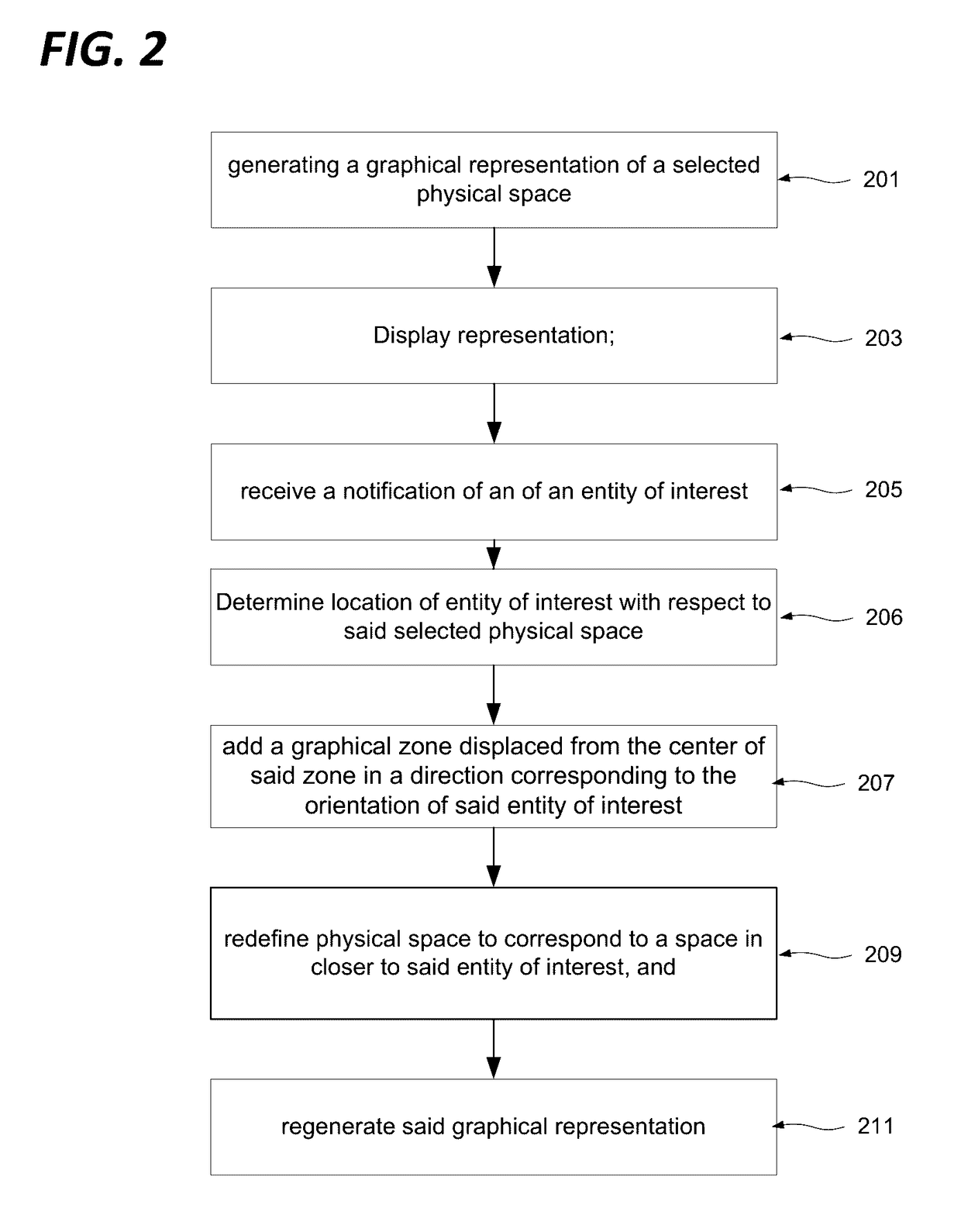
An interaction mechanism is defined for the navigation of a representation of a physical space, whereby events or entities of interest outside the current view are detected, and flagged by adding a visual indicator at or near the edge of the view closest to the entity in question. By designating the visual indicator, for example with a mouse click or by directing the user's gaze at the visual indicator, the representation is prompted to modify the representation to include the space incorporating the entity of interest. The point of view may revert to the initial point of view on a further user action or after a predetermined time, or the original point of view may be flagged as a new entity of interest which the user may then select. Multiple points of interest may be defined such that the user may jump from point to point.

Description

FIELD OF THE INVENTION[0001]The present invention relates to graphical user interfaces representing physical space.BACKGROUND OF THE INVENTION[0002]Since the development of radar during the 1930s, it has been desirable to find a means of graphically representing the physical space observed by the radar system to a user. Early systems used cathode ray oscilloscopes to represent certain characteristics of the signal for example in the A, B, E and H scopes, and eventually arrived at a two dimensional plan representation of the space being observed with the C-scope, oriented with respect to compass bearings and centred about the position of the display itself. This representation has been retained and developed ever since. Improvements in display and computer technologies have permitted the generation and display of increasingly rich information, including in particular representations of fixed features such as geographical elements, and dynamic features such as meta-data associated wit...

Claims


Application Information

Patent Timeline
Patent Type & Authority Applications(United States)
IPC IPC(8): G06F3/0485
CPCG06F3/0485G06T2207/20101G06T2207/30236G06T2207/10044G06T3/20G06F3/013G06F3/0481G06F3/0487G08G5/0026G08G5/0082
Inventor HURTER, CHRISTOPHE
Owner FRENCH CIVIL AVIATION UNIVERSITY
Learn More