Suppression of vertical crosstalk in a plasma display panel

a plasma display panel and vertical crosstalk technology, applied in the field of plasma display panels, can solve the problems of not having sufficient brightness to properly represent the image, increasing the probability of vertical crosstalk, and not accurately describing or correcting the form of vertical crosstalk

Inactive Publication Date: 2003-06-05
PANASONIC CORP
View PDF1 Cites 10 Cited by
  • Summary
  • Abstract
  • Description
  • Claims
  • Application Information

AI Technical Summary

Problems solved by technology

While the addressing discharge does produce visible light, it is not of sufficient brightness to represent the image properly.
However, there is an increased probability of vertical crosstalk.
However, the Vossen et al. paper does not describe or correct for the form of vertical crosstalk described herein.

Method used


Image

  • Suppression of vertical crosstalk in a plasma display panel
  • Suppression of vertical crosstalk in a plasma display panel
  • Suppression of vertical crosstalk in a plasma display panel

Examples


Embodiment Construction

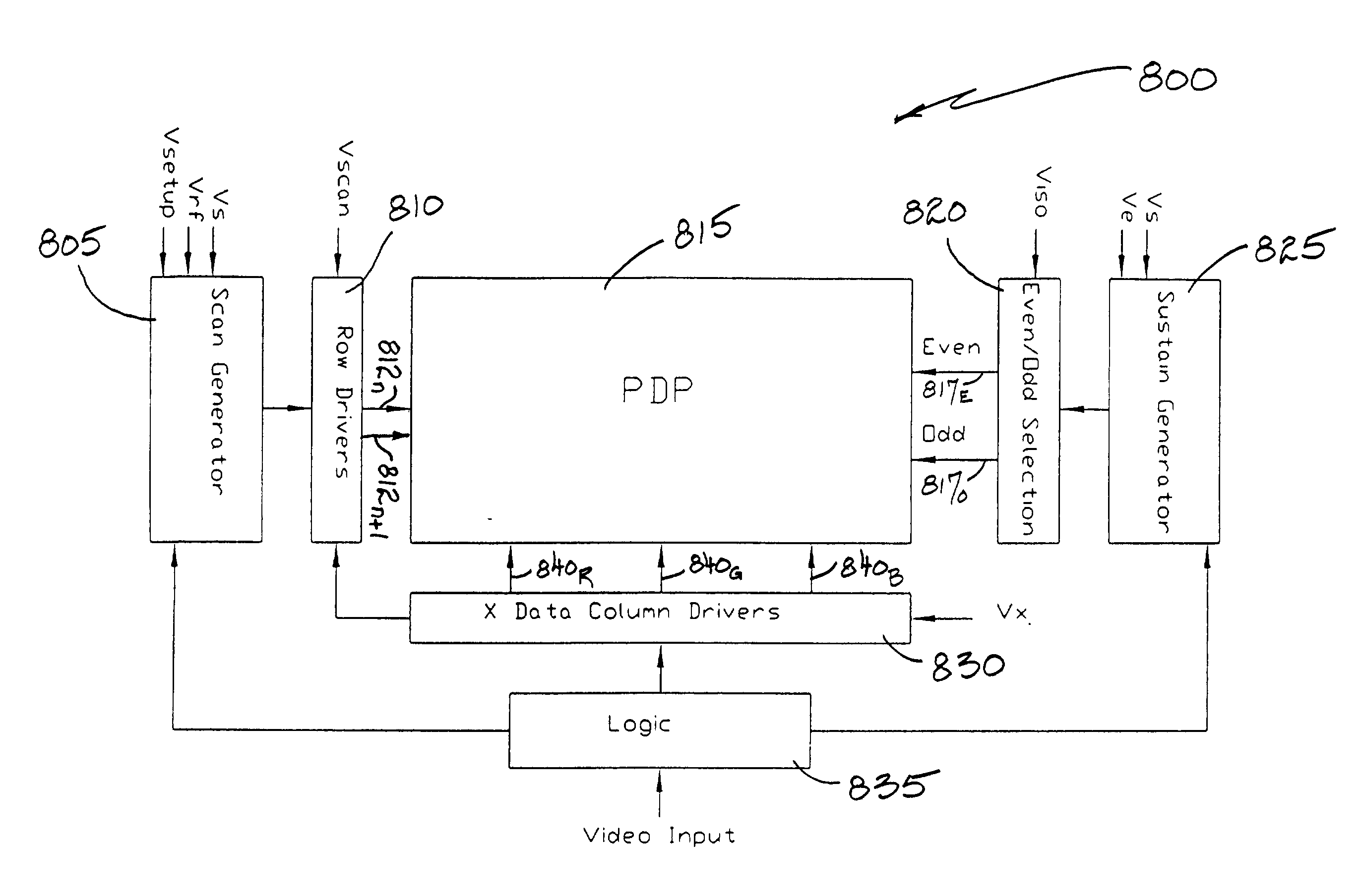
[0048] FIG. 7 is a schematic representation of a portion of a color PDP in accordance with the present invention. The PDP is organized into rows of pixels, three of which are shown, namely, a pixel 720.sub.n in row "n", a pixel 720.sub.n+1 in row "n+1", and a pixel 720.sub.n+2 in row "n+2". The rows are regarded as "odd" and "even" in an alternating pattern, where for example, row "n" is designated as an even row and row "n+1" is designated as an odd row.

[0049] The portion of the PDP shown in FIG. 7 includes an even sustain bus 712.sub.E connected to a bank of even sustain electrodes 710.sub.E, an odd sustain bus 712.sub.O connected to a bank of odd scan electrodes 710.sub.O, scan electrodes 714.sub.n, 714.sub.n+1 and 714.sub.n+2, and column electrodes 718.sub.R, 718.sub.G and 718.sub.B (for red, green, and blue, respectively). Each even sustain electrode 710.sub.E is adjacent to an odd sustain electrode 710.sub.O. For example, even sustain electrode 710.sub.E in row "n" is adjacent...


PUM


Abstract

There is provided a method for controlling sustain electrodes in a plasma display panel (PDP). The method includes enabling a first sustain electrode to produce an addressing discharge, and disabling a second sustain electrode when the first sustain electrode is producing the addressing discharge. The first sustain electrode is adjacent to the second sustain electrode.

Description

[0001] The present application is claiming priority of U.S. Provisional Patent Application Serial No. 60 / 341,506, filed on Nov. 30, 2001.[0002] 1. Field of the Invention[0003] The present invention relates to plasma display panels (PDPs), and more particularly, to an electronic waveform technique that minimizes vertical crosstalk in a PDP.[0004] 2. Background of the Art[0005] Color PDPs are well known. FIG. 1 illustrates a prior art embodiment of a color alternating current (AC) PDP, as disclosed in U.S. Pat. No. 6,118,214 to Marcotte (hereinafter "the Marcotte '214 patent"), which is incorporated herein by reference. Transparent electrodes 11 are employed on a front panel. A front plate (not shown) includes horizontal plural pairs of sustain electrodes 10 that connect transparent electrodes 11 to a sustain bus 12. A plurality of pairs of scan electrodes 14 are juxtaposed to paired sustain electrodes 10, and both electrode sets are covered by a dielectric layer (not shown) and a mag...

Claims


Application Information

Patent Timeline
Patent Type & Authority Applications(United States)
IPC IPC(8): G09G3/20G09G3/288H01J17/49
CPCG09G3/2022G09G3/2927G09G3/293G09G3/294H01J2211/323G09G2310/0224G09G2310/066G09G2320/0209G09G2310/0218H01J11/24
Inventor MARCOTTE, ROBERT G.ISOBE, NORIFUSA
Owner PANASONIC CORP
Why Eureka
Try Eureka