
Display method and display panel

a display method and display panel technology, applied in the field of display technology, can solve the problems of insufficient improvement of virtual algorithm technologies, bottlenecks limiting further improvement of resolution, and inability to reduce the dimension of sub-pixels in infinite ways, and achieve good display effect and high resolution display

Inactive Publication Date: 2016-02-18
BOE TECH GRP CO LTD +1
View PDF9 Cites 10 Cited by
  • Summary
  • Abstract
  • Description
  • Claims
  • Application Information

AI Technical Summary

Benefits of technology

The present invention aims to provide a display method and panel that can realize high resolution display with good display effect. The display method utilizes six virtual pixels that share one sub-pixel, enabling the visual resolution to be six times greater than the actual physical resolution. This is achieved using a specific display panel. The method is simple and requires small calculations, making it efficient.

Problems solved by technology

However, due to limitation of processes, the dimension of the sub-pixel cannot be infinitely reduced, which becomes a bottleneck restricting further improvement in resolution.
However, the effect of the existing virtual algorithm technologies is not good enough, some will cause defects such as image distortion, jagged lines, grid spots and the like and some will require calculations such as picture partitioning, picture layering and area ratio, resulting in complex process and large calculation amount.

Method used


Image

  • Display method and display panel
  • Display method and display panel
  • Display method and display panel

Examples


embodiment 1

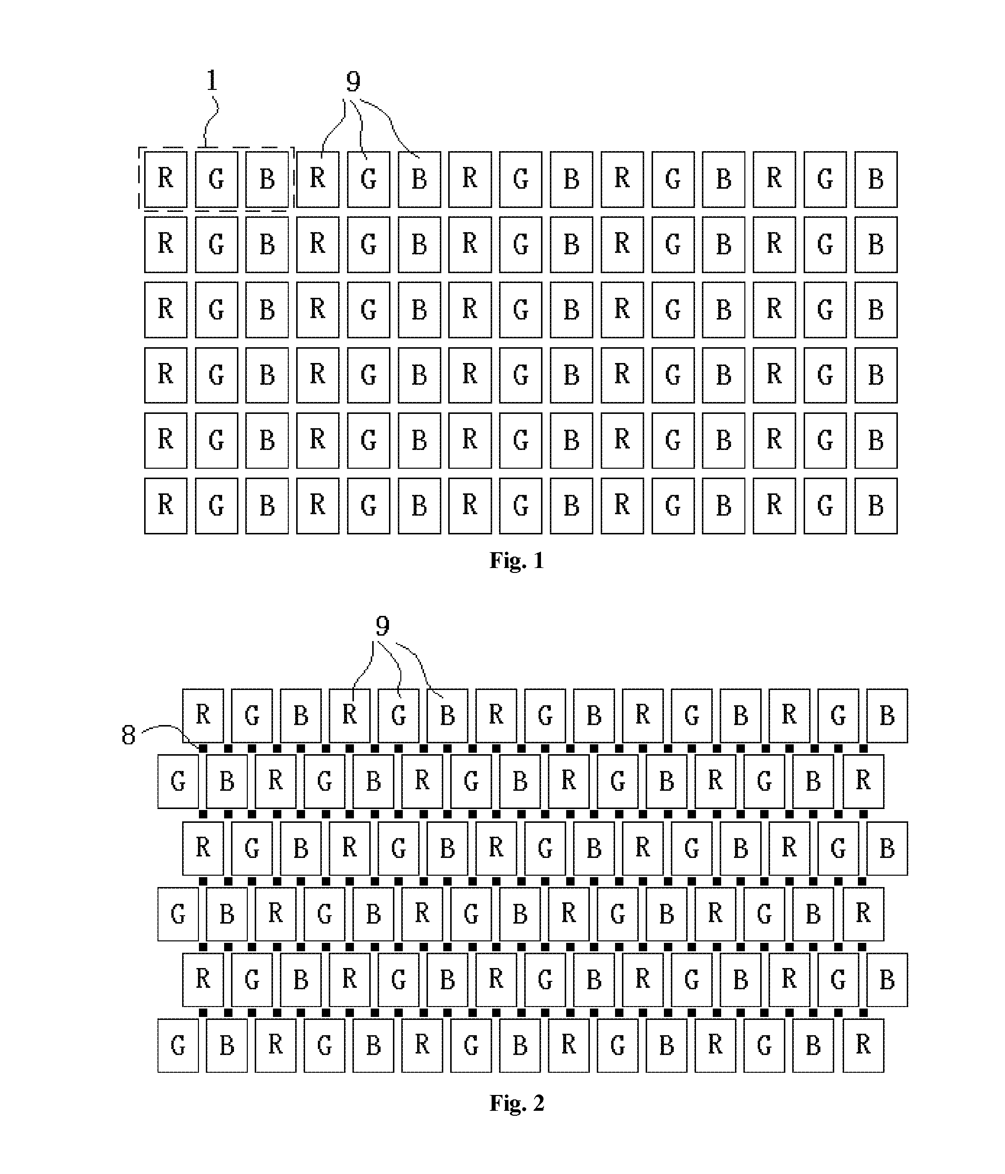
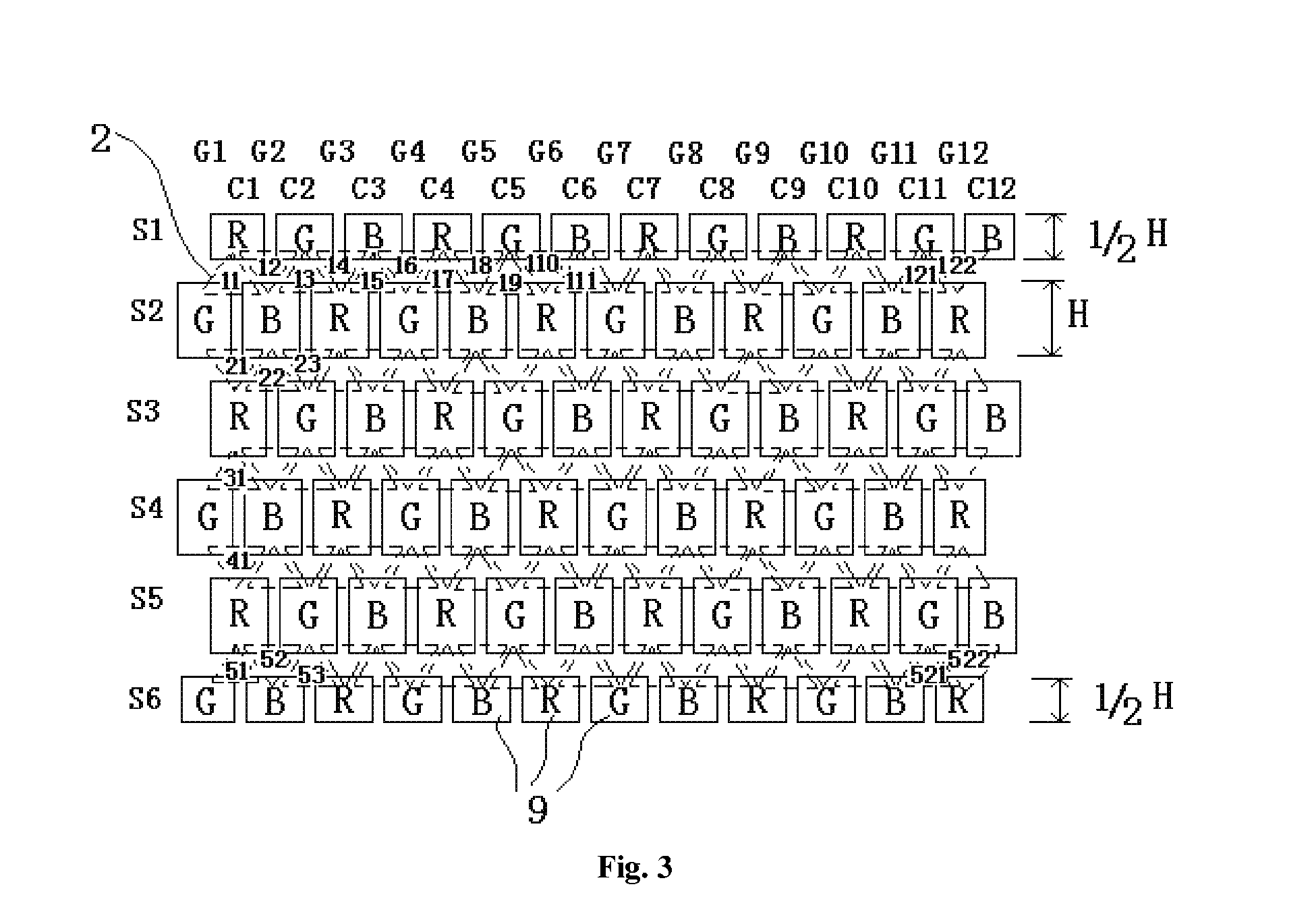
[0031]As illustrated in FIG. 2 and FIG. 3, the embodiment provides a display method, which is suitable for a display panel of the embodiment.

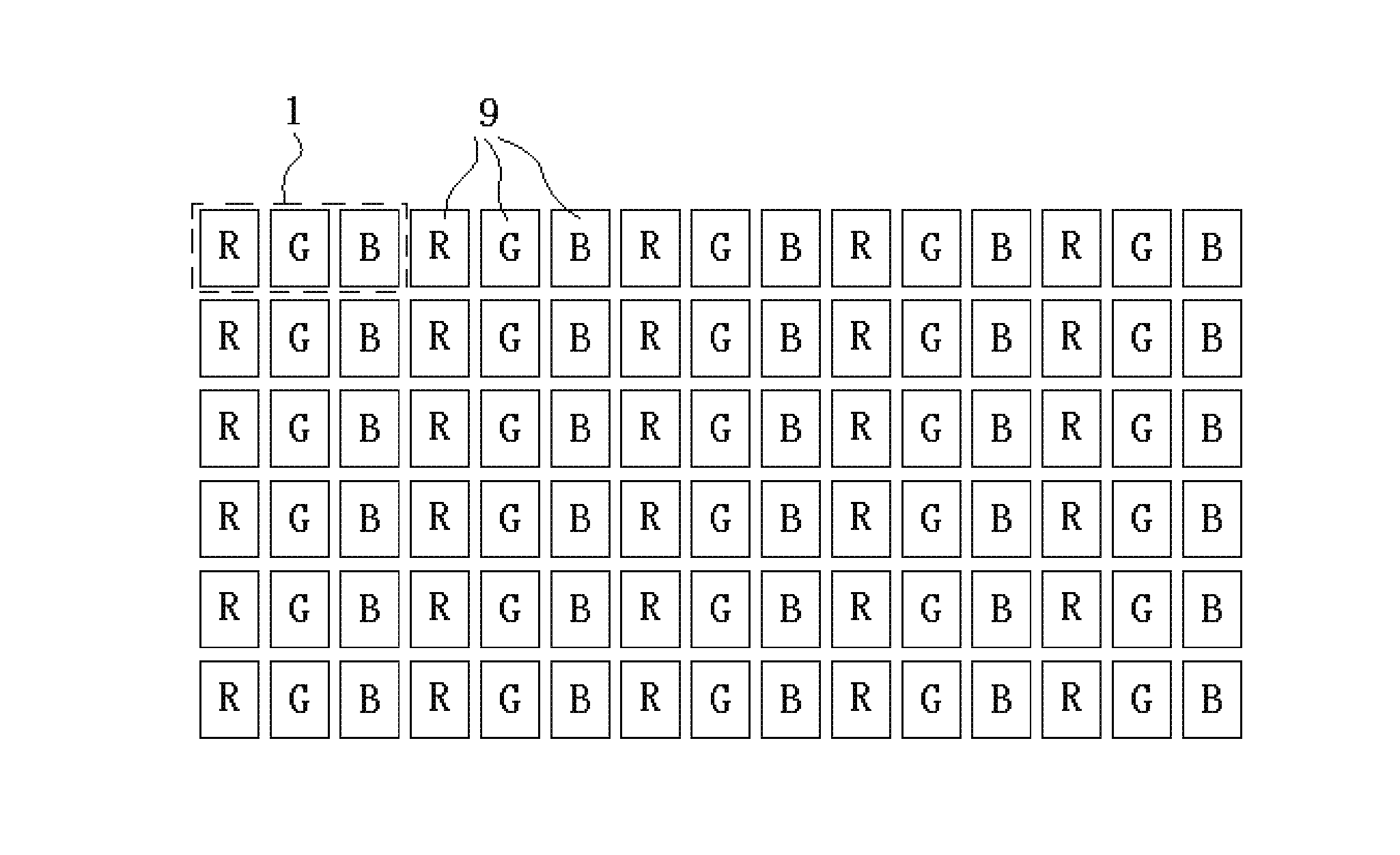
[0032]The display panel of the embodiment includes a plurality of rows of sub-pixels 9, in which the sub-pixels 9 in each row are formed by cyclically arranging sub-pixels 9 of three colors in turn, and cyclical orders of the sub-pixels 9 in the respective rows are the same. Optionally, the sub-pixels 9 of three colors are red sub-pixels 9, blue sub-pixels 9 and green sub-pixels 9, respectively, and the embodiment will be described by taking this mode as an example, i.e. the display panel of the embodiment is in an RGB mode. Certainly, the display panels in other arrangement modes, such as arrangement including other colors or arrangement in which the number of the sub-pixels in each pixel is 2, 4 or other number, also can adopt display methods similar to the present invention.

[0033]That is, as illustrated in FIG. 2, the sub-pixels 9 of three d...


PUM


Abstract

The present invention provides a display method and a display panel. The display panel comprises a plurality of rows of sub-pixels, the adjacent sub-pixels in the column direction having different colors and being staggered from each other by ½ of the sub-pixel in the row direction. The display method comprises: S1, generating an original image composed of a matrix of virtual pixels; S2, enabling the virtual pixels to correspond to sampling locations, wherein each sampling location corresponds to a virtual pixel; each sampling location is located between every two adjacent rows of the sub-pixels, and corresponds to a location between two sub-pixels in one row and a central location of a sub-pixel in the other row; and S3, calculating a display component of each sub-pixel in accordance with original components of corresponding colors of virtual pixels corresponding to the sub-pixel. The present invention is suitable for high resolution display.

Description

FIELD OF THE INVENTION[0001]The present invention relates to the field of display technology, and particularly to a display method and a display panel.BACKGROUND OF THE INVENTION[0002]As illustrated in FIG. 1, a traditional display panel includes a plurality of ‘pixels 1’ arranged in a matrix, in which each pixel 1 is composed of three adjacent red, green and blue sub-pixels 9 which are arranged in a row. Each sub-pixel 9 can independently emit light of certain luminance (of course the light has specific color), and by light mixing effect the three sub-pixels 9 together constitute an independent display ‘point’ on a screen.[0003]With the development of technology, the resolution of a display panel becomes increasingly higher, which requires reducing the dimension of the pixel (or the sub-pixel) in the display panel. However, due to limitation of processes, the dimension of the sub-pixel cannot be infinitely reduced, which becomes a bottleneck restricting further improvement in resol...

Claims


Application Information

Patent Timeline
Patent Type & Authority Applications(United States)
IPC IPC(8): G09G3/20
CPCG09G3/2003G09G2300/0426G09G2300/0452G09G3/2074G09G3/20G09G3/3208G09G2310/0232G09G2340/0457
Inventor SHI, LINGYUNDONG, XUEKIM, HYUNGKYUSUN, HAIWEIZHANG, HAOHE, QUANHUAYANG, KAI
Owner BOE TECH GRP CO LTD
Learn More