High Security Flush Plug Assembly

Inactive Publication Date: 2018-11-22
STADLER DAVID
View PDF20 Cites 4 Cited by
  • Summary
  • Abstract
  • Description
  • Claims
  • Application Information

AI Technical Summary

Benefits of technology

[0009]Accordingly, it is an object of the present invention to provide

Problems solved by technology

However, this approach has become only minimally effective, as pentagonal socket wrenches are now easily obtainable by anyone as from various supply houses such as Graingers.
In the case of a curb box using a threaded flush plug installed in a threaded bore in the flange to block access via the th

Method used


Image

  • High Security Flush Plug Assembly
  • High Security Flush Plug Assembly
  • High Security Flush Plug Assembly

Examples


Embodiment Construction

[0031]In the following detailed description, certain specific terminology will be employed for the sake of clarity and a particular embodiment described in accordance with the requirements of 35 USC 112, but it is to be understood that the same is not intended to be limiting and should not be so construed inasmuch as the invention is capable of taking many forms and variations within the scope of the appended claims.

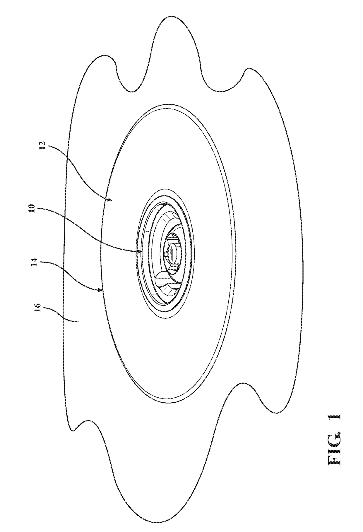
[0032]Referring to the drawings, FIG. 1 depicts a flush plug assembly 10 according to the invention installed in a threaded bore formed in a flange 12 of a curb box 14 recessed into paving 16.

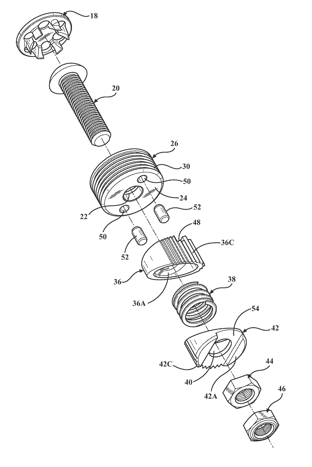
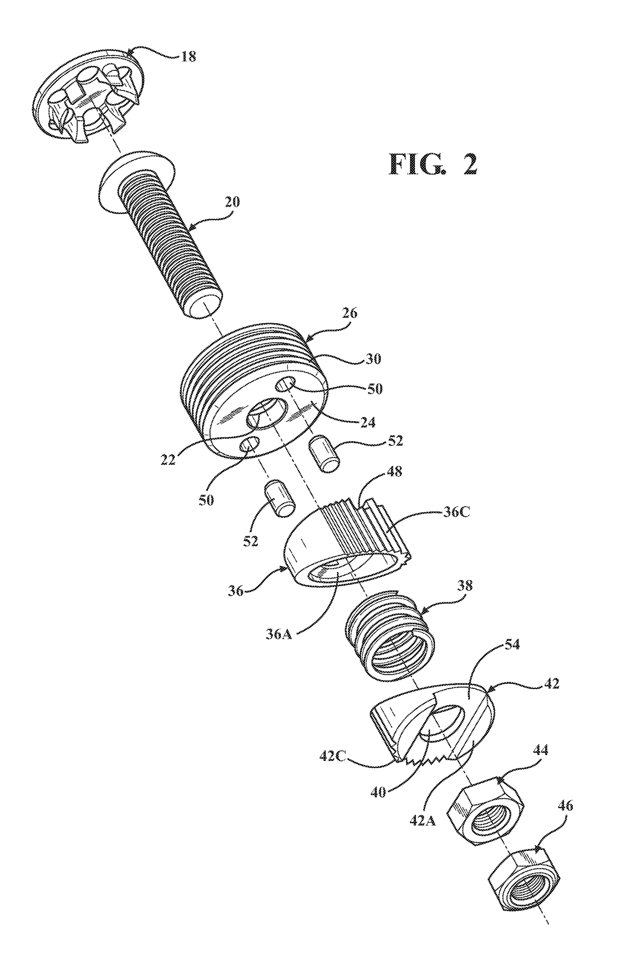
[0033]The components of the flush plug assembly 10 are shown in FIG. 2, which includes a cover 18 placed atop the flush plug assembly 10 after installation (FIG. 8).

[0034]A stainless steel security bolt 20 passes through a hole 22 in a bottom wall 24 of a flush plug body 26 having an external thread 30 received into an internal thread 32A a bore in the flange 12 of the curb box 14 (...


PUM


Abstract

A high security flush plug assembly includes a flush plug body threaded into a flush plug bore in a curb box flange, with a security bolt extending down through a hole in the flush plug body. The security bolt is received in a locking mechanism mounted thereto and extending below the flush plug body which when operated acts to engage the inside of the stand pipe to prevent any rotation of the flush plug body, preventing its removal until the locking mechanism is operated to release the engagement with the stand pipe.

Description

CROSS REFERENCE TO RELATED APPLICATION[0001]This application claims the benefit of U.S. provisional patent application No. 62 / 508,019 filed on May 18, 2017.BACKGROUND OF THE INVENTION[0002]This invention concerns shut off valves such as are usually associated with utility supply lines to a customer.[0003]A shut off valve is normally provided in order to be able to shut off service for maintenance or to end service for nonpaying customers which is only accessible through a hole in a curb box. A flush plug threaded into the hole must be removed in order to allow operation of the shut off valve by means of a long tool inserted through the hole after the flush plug is removed. The tool is long enough to extend down to the shutoff valve at the bottom of the stand pipe.[0004]In order to provide access to the shut off valve only to authorized personnel, the threaded flush plug is typically provided with a pentagonal shaped socket wrenching feature on the top of the flush plug which require...

Claims


Application Information

Patent Timeline
IPC IPC(8): F16K35/06
CPCF16K35/06F16K35/10
Inventor STADLER, DAVID
Owner STADLER DAVID
Why Eureka
Try Eureka