Adjustable valve pin assembly

a valve pin and assembly technology, applied in the field of valve gate systems, can solve the problems of undue wear of both the valve pin and the gate, poor gate vestige, and fracture of the mold around the ga

Active Publication Date: 2010-04-27
TRAKAS PANOS
View PDF37 Cites 5 Cited by
  • Summary
  • Abstract
  • Description
  • Claims
  • Application Information

AI Technical Summary

Benefits of technology

[0006]In accordance with this invention, a novel valve pin adjustment system is provided for use in valve gate injection molding applications which enables adjustments to the positioning of the valve pin without necessitating removal of manifold plates and valve assembly components, including the valve pins. A piston that captures the head of the valve pin includes a cylindrical body having upper and lower internally threaded bores of respective first and second diameters. Preferably the upper bore is oppositely threaded with respect to the lower bore, and the upper and lower bores are in axial alignment with each other and with the valve pin. First and second externally threaded cylindrical valve pin positioning members are respectively threadedly received in the lower and upper bores. Each of the threaded positioning members includes a head portion and a tip portion. The head portions are each provided with a hex-shaped recess or equivalent tool-engaging surface for receiving a hex key wrench or the like. The tip of the first positioning member is in contact with the head portion of the valve pin to locate the valve pin, while the tip of the second positioning member is in contact with the head of the first positioning member to lock the first positioning member in place, so that first positioning member is restrained from unscrewing.
[0008]In another aspect of the invention, the piston is received in a cylinder that also serves as the pressure pad and insulator between the top clamp plate and the manifold of the hot runner system. The well in the top clamp plate which overlies the cylinder and piston includes one or more radially-extending slots that, upon rotation of the piston, align with similarly radially-extending slots on the upper end of the piston. The specially-designed wrench may then be used which has one or more blades that engage the aligned slots, thus preventing rotation of the piston relative to the top clamp plate when the first and second threaded positioning members are being screwed into the piston.

Problems solved by technology

If the valve pin does not extend far enough into the gate, it will not seat tightly when in the closed position, leading to a poor gate vestige.
If the valve pin extends too far toward the gate, the tip of the pin will repeatedly impact the gate on closing, thus causing undue wear of both the valve pin and the gate and, potentially, fracture of the mold around the gate.
Typically, final adjustment of the positioning of the valve pin is a complicated and time-consuming procedure.
It is, obviously, an exacting and time consuming process.

Method used


Image

  • Adjustable valve pin assembly
  • Adjustable valve pin assembly
  • Adjustable valve pin assembly

Examples


Embodiment Construction

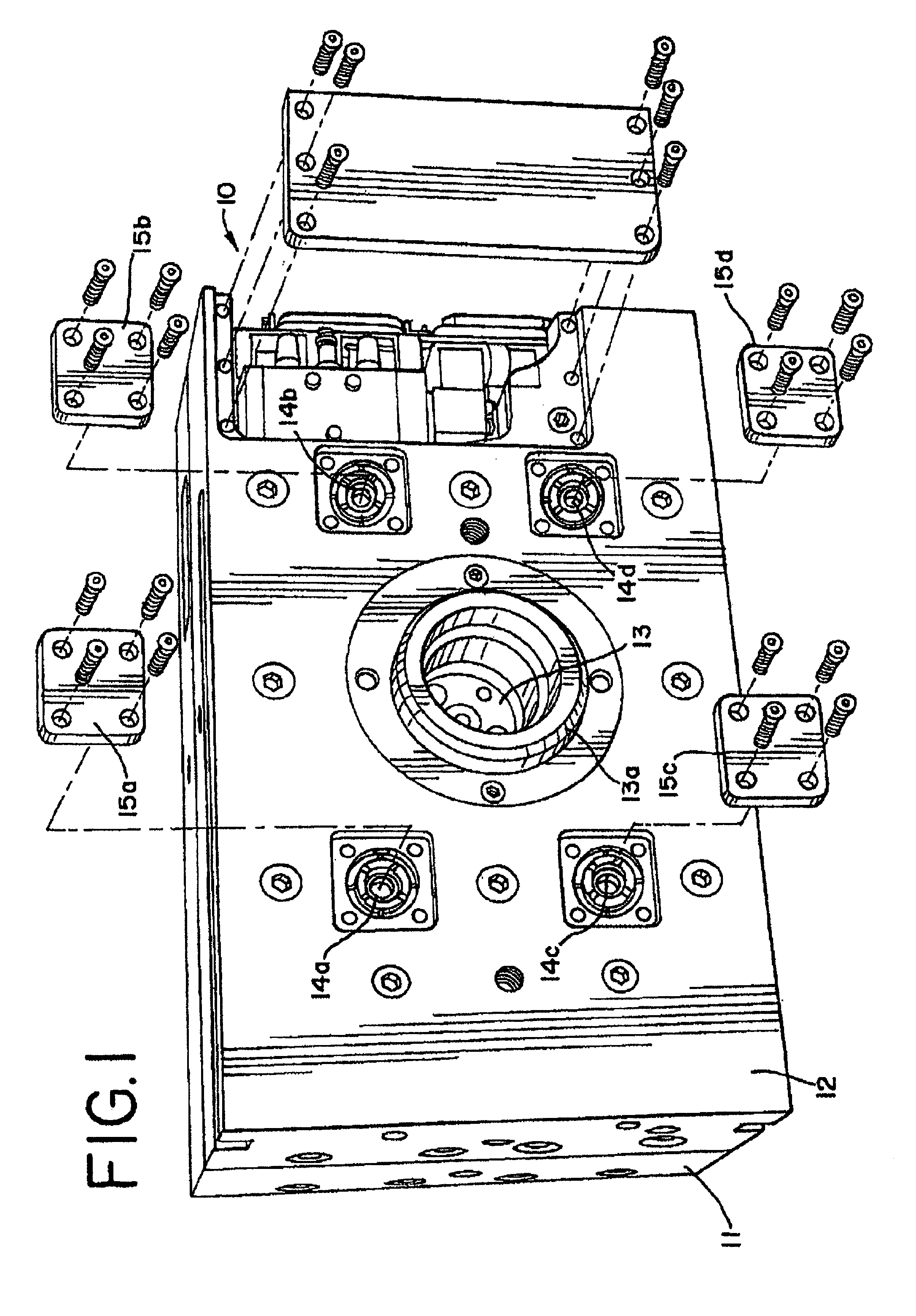
[0023]Referring to the drawings, and, in particular with reference to FIG. 1, a manifold system for a multi-cavity injection molding apparatus is generally depicted by the reference numeral 10 having a manifold plate 11 and a clamp plate 12. The hot runner manifold (not seen in FIG. 1) is clamped between the two plates 11 and 12, which are secured together by a plurality of bolts. The clamp plate 12 includes a locating ring 13a that fits into the bore of a platen of the molding machine for delivering pressurized melt to the system through an intake nozzle 13 on the manifold. A plurality of nozzle-access compartments or wells 14a, 14b, 14c and 14d (one for each nozzle) is provided. The associated cover plates are shown removed and are respectively designated by the reference numerals 15a, 15b, 15c and 15d. While the illustrated embodiment shows a system with four nozzles, any number of nozzles may be used, depending upon the particular application.

[0024]As is generally shown in FIG. ...


PUM

PropertyMeasurementUnit
diametersaaaaaaaaaa
torqueaaaaaaaaaa
axial lengthaaaaaaaaaa

Abstract

The valve pin adjustment system is provided for use in valve gated injection molding applications which enables adjustments to the positioning of the valve pin without necessitating removal of the clamping plates and valve assembly components, including valve pins. A piston associated with the valve pin includes a cylindrical body having first and second co-axially aligned internally threaded bores of respective first and second diameters. Preferably, the threads formed in the first and second bores are of the opposite hand. First and second externally-threaded cylindrical valve pin positioning members are respectively received in the first and second bores. Each of the positioning members includes a head portion and a tip portion. The tip of the second positioning member is in contact with the head of the first positioning member to lock the first positioning member in place, and the tip of the first positioning member is in contact with a head portion on the valve pin to locate the valve pin.

Description

CROSS-REFERENCE TO RELATED APPLICATION[0001]This application claims the benefit of the filing date of provisional application Ser. No. 60 / 480,777, filed on Jun. 23, 2003.BACKGROUND OF THE INVENTION[0002]The present invention generally relates to valve gate systems wherein a reciprocating valve pin opens and closes a melt passageway in injection molding applications. More particularly, this invention relates to valve pin assembly and a method for adjusting valve pin position to ensure proper opening and closing of the melt passageway during injection molding operations.[0003]Valve gated injection molding systems are known in which pistons are actuated pneumatically or hydraulically to reciprocate the valve member. In general, such systems require that the components, in particular the valve pin and its associated piston, be made to very close tolerances to allow for thermal expansion so that, when at operating temperatures, the front end of the valve pin seats precisely in the gate t...

Claims


Application Information

Patent Timeline
Patent Type & Authority Patents(United States)
IPC IPC(8): B29C45/23B29C45/28
CPCB29C45/2806B29C2045/2848B29C2045/2889
Inventor TRAKAS, PANOS
Owner TRAKAS PANOS
Why Eureka
Try Eureka