Image reading apparatus

Active Publication Date: 2019-01-03
SEIKO EPSON CORP
View PDF1 Cites 1 Cited by
  • Summary
  • Abstract
  • Description
  • Claims
  • Application Information

AI Technical Summary

Benefits of technology

[0007]An advantage of some aspects of the invention is to provide an image reading apparatus whic

Problems solved by technology

In this case, it is concerned that there is a problem that stapled portions of transported documents are torn.
Therefore, when the document feeding apparatus is installed at a place affected by the magnetic field, the effect of the magnetic field may become a disturbance noise and the disturbance noise may have a bad influence on detection accuracy of the binding needle in the document feeding apparatus.
On the other hand, the magnetic field generated by the metal detector itself may have a

Method used


Image

  • Image reading apparatus
  • Image reading apparatus
  • Image reading apparatus

Examples


Example

First Embodiment

Overview of Image Reading Apparatus

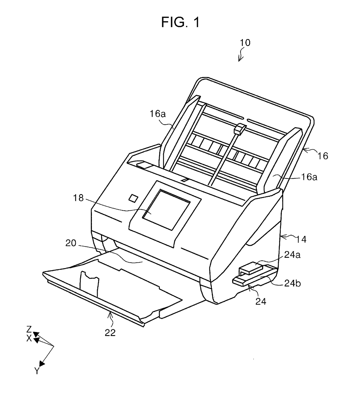
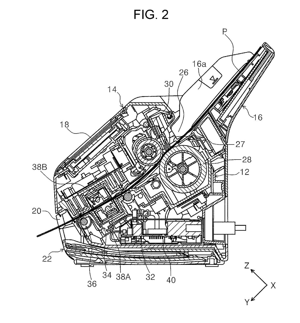
[0057]In FIG. 1, a scanner 10 will be described as an example of the image reading apparatus. The scanner 10 includes a main body portion 12 (see FIG. 2) and a housing 14 which covers the main body portion 12 and constitutes an external surface of the scanner 10.

[0058]A document setting unit 16 which sets the document is provided at an end of the main body portion 12 on a rear surface side of the apparatus. The document setting unit 16 is configured to be able to support the document in an inclined posture. A plurality of sheets of documents can be set in the document setting unit 16. The document setting unit 16 is provided with a pair of edge guides 16a which can be moved in directions to approach each other or in directions to depart from each other and is configured to guide a side portion of the document mounted in the document setting unit 16.

[0059]A user interface unit 18 is provided on a front surface side of the housing 14 ...

Example

Modification Example of Embodiment

[0137](1) Next, a binding member detector 56 (modification example of binding member detector 24) will be described with reference to FIG. 14. In the present embodiment, the distance L1 between the first portion 24a and the second portion 24b is fixed, but instead of this configuration, the distance L2 between a first portion 56a and a second portion 56b may be changeable. Specifically, a position adjusting unit 56c is provided in the first portion 56a or the second portion 56b and one of the first portion 56a and the second portion 56b may be displaceable in a direction to approach to or separate from the other of the first portion 56a and the second portion 56b. As an example, by the first portion 56a approaching the second portion 56b, it is possible to adjust the interval between the first portion 56a and the second portion 56b. The position adjusting unit 56c is configured of, for example, a guide mechanism, a link mechanism, or the like.

[0138]...


PUM


Abstract

There is provided an image reading apparatus including: a reading unit that reads a document; a document transport unit that transports the document toward the reading unit; a binding member detector that detects a binding member binding the document by detecting a change in a magnetic field when the document passes through the magnetic field; a document detector that detects passage of the document when the document passes through the binding member detector; and a controller that receives information on the document detected by the document detector and information on the change in the magnetic field detected by the binding member detector, in which in a case where the binding member detector detects the change in the magnetic field in a document undetected state in which the document detector does not detect the passage of the document, the controller executes a predetermined process.

Description

BACKGROUND1. Technical Field[0001]The present invention relates to an image reading apparatus which reads a document.2. Related Art[0002]In an image reading apparatus represented by a scanner, in some case, a user mistakenly sets a document bundle stapled as it is and a feeding job is started. In this case, it is concerned that there is a problem that stapled portions of transported documents are torn.[0003]In view of the problem, JP-A-9-077282 discloses a document feeding apparatus including a non-contact metal detector for detecting a binding needle in an upstream portion in a document transport direction rather than a transport roller for separating the documents one by one and transporting the documents. In JP-A-9-077282, when the metal detector detects the binding needle after rotation of the transport roller, that is, a document feeding operation is started, the document feeding apparatus stops to drive the transport roller or the like.[0004]In the related art, various types o...

Claims


Application Information

Patent Timeline
IPC IPC(8): H04N1/00
CPCH04N1/00037H04N1/00639H04N1/00689H04N1/0057H04N1/00795H04N1/00814H04N1/04
Inventor SHIOTA, TAKAYUKI
Owner SEIKO EPSON CORP
Why Eureka
Try Eureka