Cannulated screw

a cannula and screw technology, applied in the direction of internal osteosynthesis, fasteners, osteosynthesis devices, etc., can solve the problems of difficult to accurately insert the location of the guide wire needs, and the difficulty in accurately inserting the guide wire into the hole, so as to achieve easy insertion into the connection hole and quickly and safely remove the

Active Publication Date: 2019-01-24
INJE UNIV IND ACADEMIC COOP FOUND
View PDF1 Cites 0 Cited by
  • Summary
  • Abstract
  • Description
  • Claims
  • Application Information

AI Technical Summary

Benefits of technology

[0010]According to a cannulated screw of the present disclosure, a shape of a head portion contacting a guide wire has a curved surface, in which a center portion is concave, to guide the guide wire to be located at the center, and thus a connection hole of a cannulated screw can be easily found.
[0011]Also, a washer having a curved surface, in which a center portion is concave, is further provided to guide the guide wire to be located at the center even in a range wider than the head portion, and thus the guide wire can be easily inserted into the connection hole. Accordingly, the cannulated screw can be quickly and safely removed.

Problems solved by technology

However, it is difficult to accurately insert the guide wire into the hole, i.e., the center portion, because it is difficult to identify the fractured region with naked eyes, and there is inconvenience that a location of the guide wire needs to be indirectly checked by using an apparatus, such as a C-arm during insertion.
Also, when the inserted guide wire deviates from the center portion of the cannulated screw, it is difficult to insert the guide wire into the hole, and thus the guide wire needs to be inserted again.

Method used


Image

  • Cannulated screw
  • Cannulated screw
  • Cannulated screw

Examples


Embodiment Construction

Technical Problem

[0005]Provided is a cannulated screw that is easily removed from a fractured region because a hole of the cannulated screw is easily found even when a location of a guide wire deviates from a center portion.

Solution to Problem

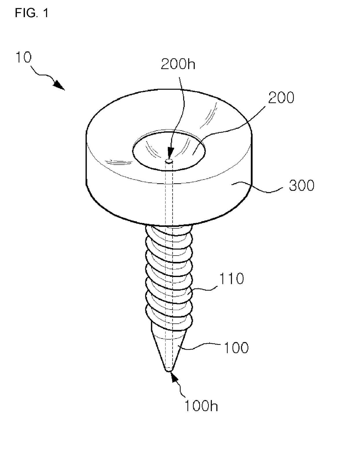
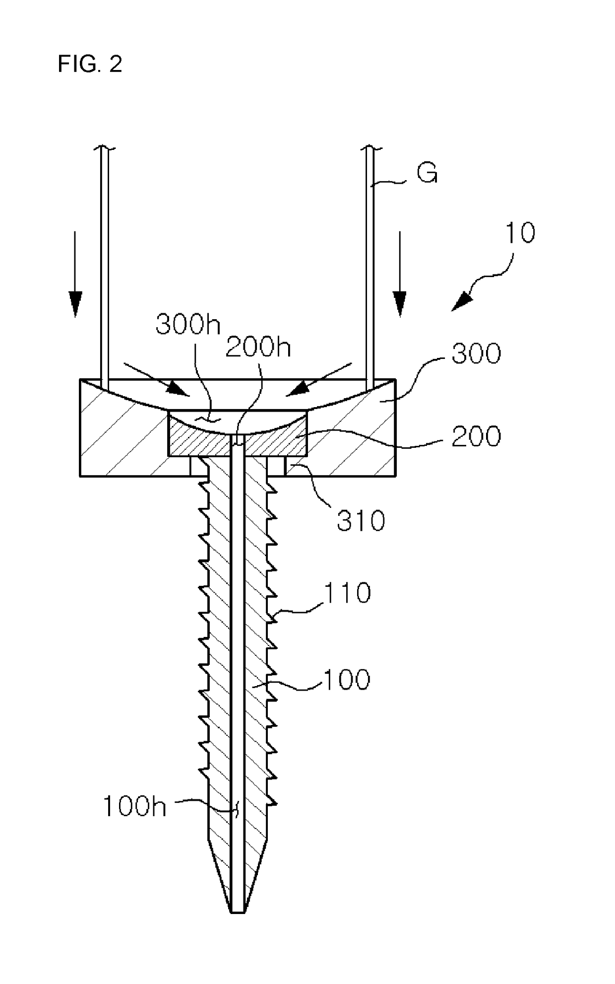
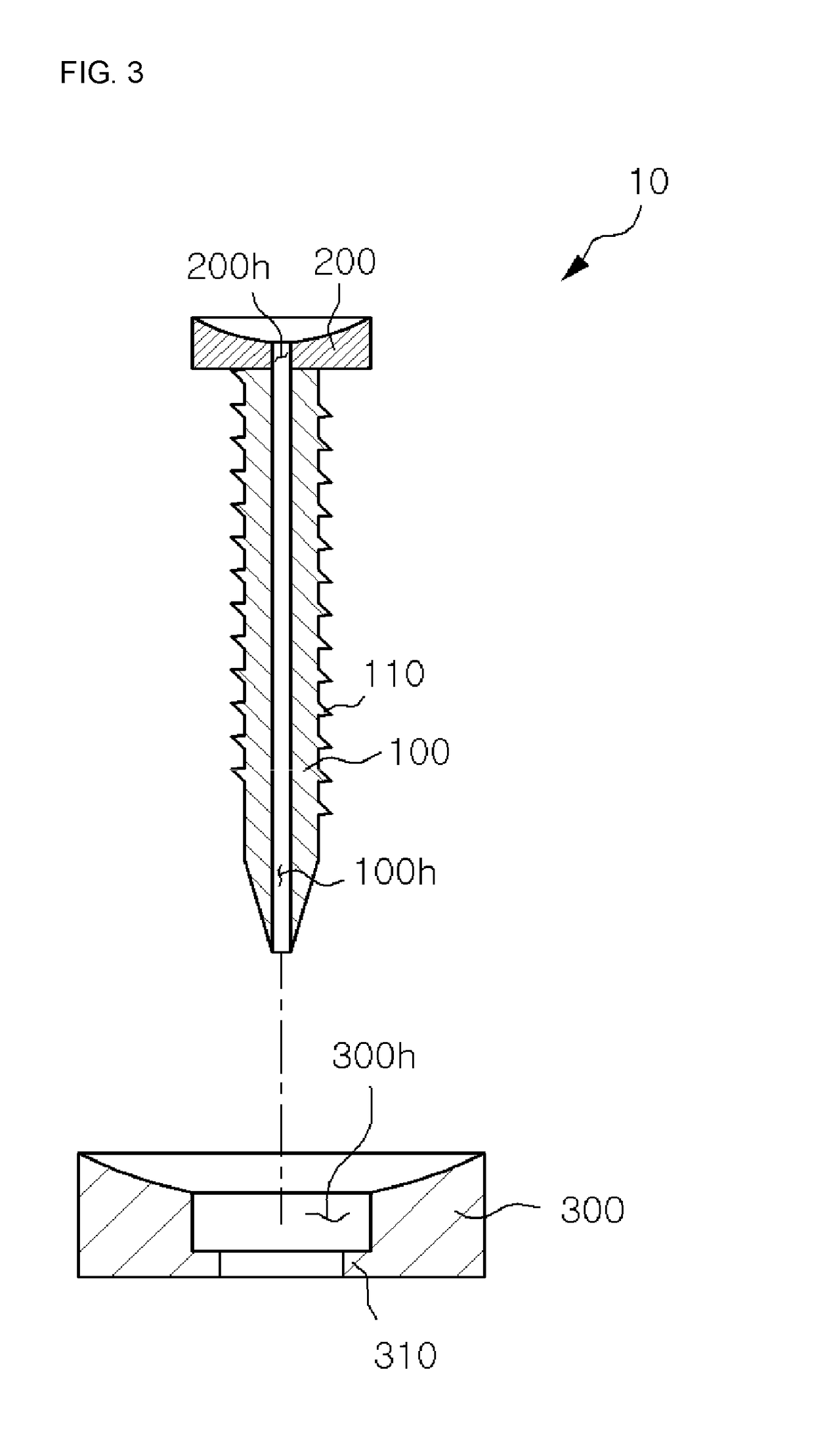
[0006]According to an aspect of the present disclosure, a cannulated screw includes: a body portion that includes a screw thread formed by protruding along an outer surface and has a through-hole at a center of the body portion; and a head portion that has one side surface combined to one end of the body portion, another side surface formed in a curved surface in which a center portion has a concave shape, and a connection hole communicating with the through-hole at a center of the head portion.

[0007]The cannulated screw may further include a washer that has an insertion hole into which the head portion is inserted at a center of the washer, includes, at one side surface, an accommodating portion where the head portion is accommodated by being ...


PUM


Abstract

A cannulated screw includes: a body portion that comprises a screw thread formed by protruding along an outer surface and has a through-hole at a center of the body portion; and a head portion that has one side surface combined to one end of the body portion, another side surface formed in a curved surface in which a center portion has a concave shape, and a connection hole communicating with the through-hole at a center of the head portion.

Description

TECHNICAL FIELD[0001]The present disclosure relates to a cannulated screw, and more particularly, to a cannulated screw having a hole penetrating therethrough to be inserted into a bone.BACKGROUND ART[0002]Generally, a cannulated screw is used to be inserted into a fractured bone, fixed to the bone, and then removed after a certain period of time. Such a cannulated screw has a hole penetrating a center portion, and when used for a fractured region that is difficult to be identified with naked eyes, a guide wire may be inserted into the hole. In other words, the guide wire is pre-installed at the fractured region, the guide wire is penetrated through the hole of the cannulated screw, and then the cannulated screw is moved along the guide wire and fixed to the fractured region. On the other hand, when the cannulated screw is to be removed, the guide wire is inserted into the hole of the cannulated screw at a location where the cannulated screw is fixed, and then the cannulated screw i...

Claims


Application Information

Patent Timeline
Patent Type & Authority Applications(United States)
IPC IPC(8): A61B17/86A61B17/88
CPCA61B17/864A61B17/8897A61B17/8695A61B17/8605A61B17/88A61B17/86
Inventor KWON, YONGUK
Owner INJE UNIV IND ACADEMIC COOP FOUND
Why Eureka
Try Eureka