Image reading apparatus

a technology of image reading and reading device, which is applied in the direction of electrical apparatus, thin material handling, pictoral communication, etc., can solve the problem of document damage between the sensors

Active Publication Date: 2019-01-31
SEIKO EPSON CORP
View PDF0 Cites 8 Cited by
  • Summary
  • Abstract
  • Description
  • Claims
  • Application Information

AI Technical Summary

Benefits of technology

[0008]According to this aspect of the invention, the second detection sections are disposed between the first detection sections in the medium width direction, and the controller determines whether to stop transporting the medium or continue transporting the medium based on the results of detection by the first detection sections and the second detection sections. Accordingly, transport states that are allowable transport states but determined to be abnormal by known skew detection structures can be detected as allowable transport states. Consequently, unnecessary stop in medium transport can be reduced.
[0026]According to this aspect, if at least one of the downstream side detection sections has detected the medium and the upstream side detection section has not detected the medium, the controller stops transporting the medium. With this configuration, a problem in which end portions in the medium width direction are transported forward and the transport of the medium is delayed in a region between the downstream side detection sections can be detected, and the transport of the medium can be stopped. Accordingly, the medium can be prevented from being largely damaged to cause a paper jam.

Problems solved by technology

Furthermore, even if the document has been detected by the pair of document-width sensors 19, in some cases, the document may be damaged between the sensors, and such an abnormal state may not be detected by such known structures.

Method used


Image

  • Image reading apparatus
  • Image reading apparatus
  • Image reading apparatus

Examples


first embodiment

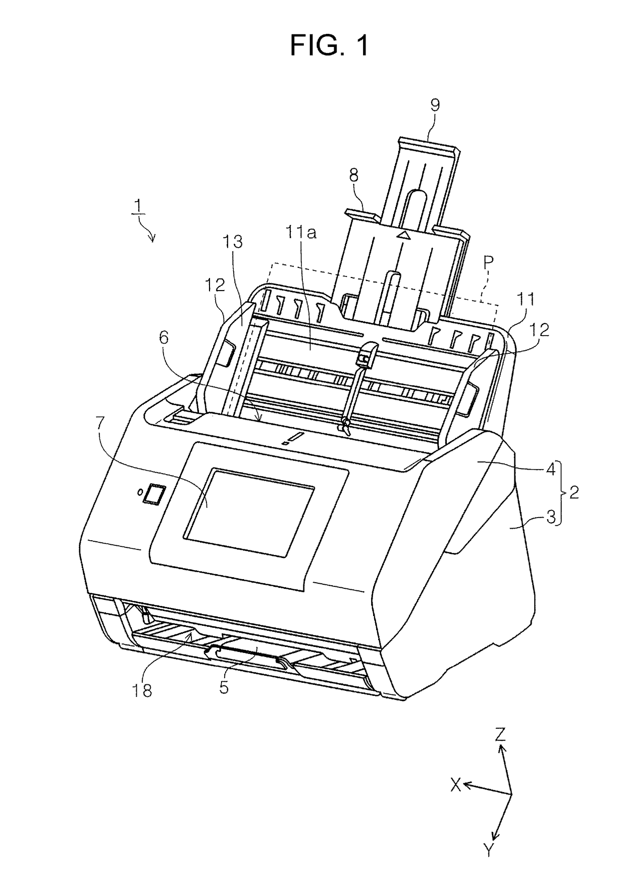
[0047]First, an image reading apparatus according to an embodiment of the invention will be briefly described. In this embodiment, as an example image reading apparatus, a document scanner (hereinafter, simply referred to as a scanner 1) that can read an image on at least one of the front surface and the back surface of a medium will be described.

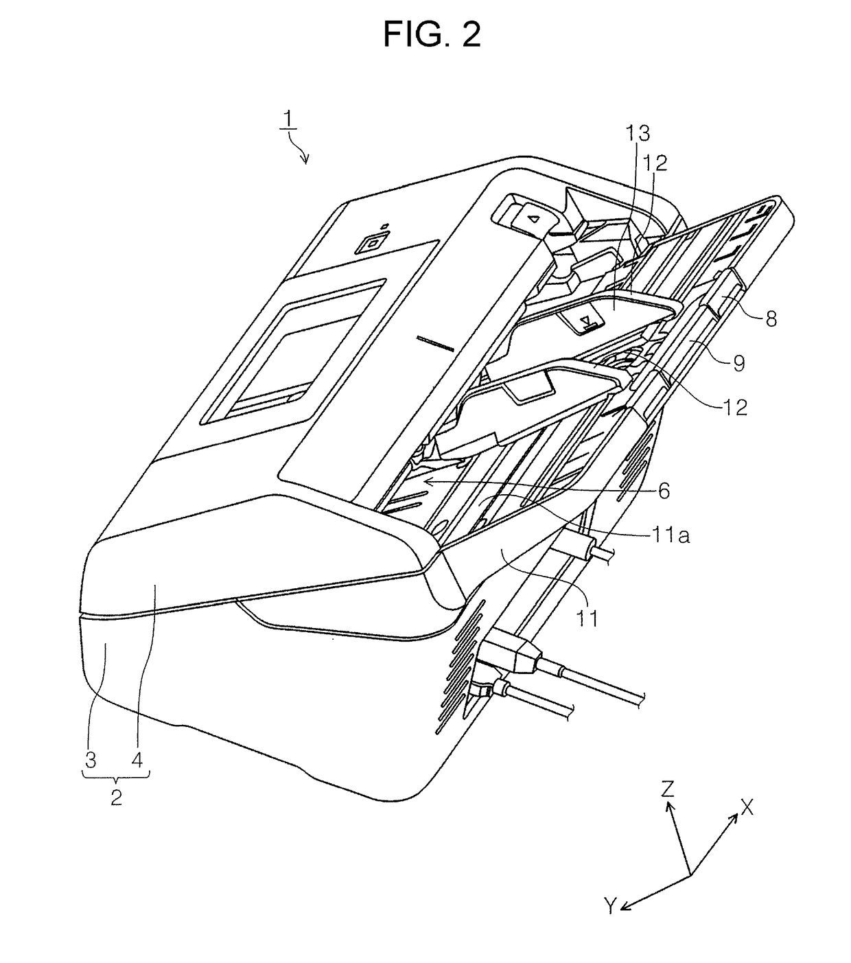
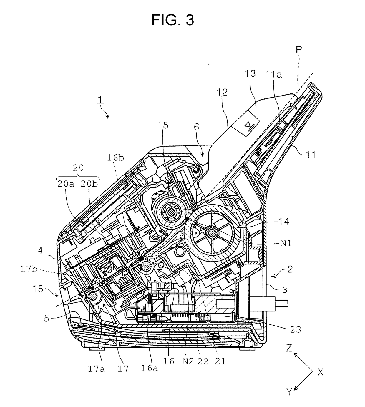
[0048]FIG. 1 is an external perspective view of the scanner according to the embodiment of the invention. FIG. 2 is a perspective view of the scanner according to the embodiment viewed from another angle. FIG. 3 is a side cross-sectional view of a sheet transport path in the scanner according to the embodiment. FIG. 4 is a perspective view illustrating a lower unit from which an upper unit has been detached. FIG. 5 is a schematic plan view illustrating main components according the first embodiment. FIG. 6 illustrates transport states of sheets. FIG. 7 to FIG. 10 illustrate the other transport states of the sheets.

[0049]In the X-Y-Z coordin...

second embodiment

[0087]A second embodiment will be described with reference to FIG. 11 to FIG. 13. FIG. 11 is a schematic plan view illustrating main components according the second embodiment. FIG. 12 is a schematic plan view illustrating an example problem occurred when end portions of a sheet in the width direction are transported forward and a central area is delayed. FIG. 13 is a schematic plan view illustrating another example problem occurred when end portions of a sheet in the width direction are transported forward and a central area is delayed. In the following embodiments, the same reference numerals are given to components similar to those in the first embodiment, and their descriptions will be omitted. In the second embodiment, in the medium transport direction, downstream side detection sections 31 and an upstream side detection section 32 for detecting a sheet are disposed between the first positions N1, which are the nip positions of the feeding rollers 14 and the separation rollers ...

third embodiment

[0095]A third embodiment will be described with reference to FIG. 14. FIG. 14 is a schematic plan view illustrating main components according the third embodiment. The third embodiment includes a third detection section 33 for detecting a sheet in addition to the first detection sections 21 and the second detection sections 22 described in the first embodiment.

[0096]The third detection section 33 has a configuration similar to that of the upstream side detection section 32 in the second embodiment. Specifically, the third detection section 33 is disposed between the pair of the second detection sections 22 (correspond to the pair of the downstream side detection sections 31 in the second embodiment) in the medium width direction and on the downstream side of the first positions N1 and upstream side of the pair of the second detection sections 22 in the medium transport direction as illustrated in FIG. 14.

[0097]The third embodiment includes the first detection sections 21, the second...


PUM


Abstract

An image reading apparatus includes a pair of first detection sections disposed between first positions for the feeding rollers and the separation rollers for nipping and second positions for the transport roller pair for nipping, and a pair of second detection sections disposed between the first detection sections and the second positions in the medium transport direction. The second detection sections are disposed between the first detection sections in the medium width direction, and a controller determines whether to stop transporting the medium or continue transporting the medium based on the results of detection by the first detection sections and the second detection sections.

Description

BACKGROUND1. Technical Field[0001]The present invention relates to an image reading apparatus that reads images on documents.2. Related Art[0002]Some scanners, which are example image reading apparatuses, include a plurality of medium sensors for detecting a document (medium) to be read in a reading section so as to detect skewing of the document and an occurrence of a paper jam (for example, JP-A-2016-184827).[0003]JP-A-2016-184827 describes a skew detecting member for detecting a skewed medium by using a pair of document-width sensors 19 provided in a medium width direction, and a feed-out sensor 17 that is disposed on an upstream side of the document-width sensors 19 in a medium transport direction and between the pair of the document-width sensors 19 in the medium width direction. If the skew amount detected by the skew detecting member exceeds a predetermined amount, the document transport is stopped.[0004]As illustrated in FIG. 6 in JP-A-2016-184827, when the width of the docu...

Claims


Application Information

Patent Timeline
Patent Type & Authority Applications(United States)
IPC IPC(8): H04N1/00
CPCH04N1/00793H04N1/00718H04N1/00689H04N1/00602H04N1/00628B65H7/06B65H26/02H04N1/00H04N1/00734H04N1/0074H04N1/00745H04N1/3878
Inventor SHIOTA, TAKAYUKI
Owner SEIKO EPSON CORP
Why Eureka
Try Eureka