
Multi-plate faceplate for a processing chamber

Active Publication Date: 2019-02-14
APPLIED MATERIALS INC
View PDF8 Cites 1 Cited by
  • Summary
  • Abstract
  • Description
  • Claims
  • Application Information

AI Technical Summary

Benefits of technology

This patent describes a gas discharge apparatus for use in semiconductor processing chambers. The apparatus includes a multi-piece faceplate with multiple openings. The first plate has many openings, and the second plate has many openings that match the first plate's openings. The second plate's openings have a conical portion that tapers towards the second surface of the plate. The conical portion is coated with a protective coating. The faceplate also includes a protrusion that sticks out from the first surface of the second plate and into a recess on the first surface. The recess is connected to the second plate's opening. This design allows for more efficient gas discharge and improved semiconductor processing.

Problems solved by technology

Increasing device densities have resulted in structural features having decreased spatial dimensions.
The plasma gas species may be highly corrosive, and therefore corrode processing chamber components and other surfaces that are exposed to the plasma.
This results in direct exposure of the uncoated surfaces to process gases, plasma and plasma byproducts, as well as the cleaning materials, which are often corrosive or erosive to the unprotected surface.
The useful lifetime of the faceplate is reduced as a result, requiring premature replacement thereof.
Similarly, where a showerhead is configured with gas discharge openings of a similar configuration, the same issues arise.

Method used


Image

  • Multi-plate faceplate for a processing chamber
  • Multi-plate faceplate for a processing chamber
  • Multi-plate faceplate for a processing chamber

Examples


Embodiment Construction

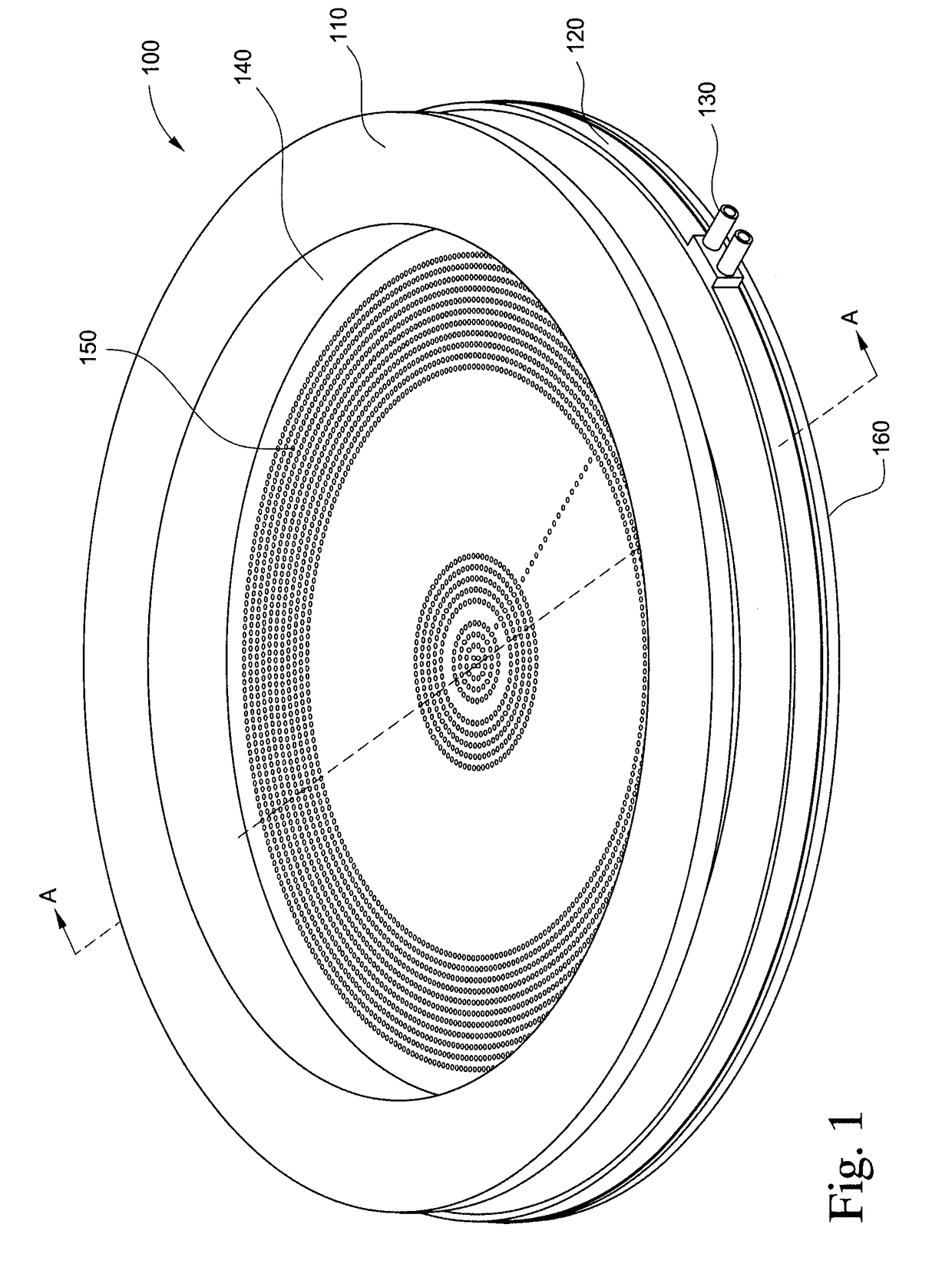
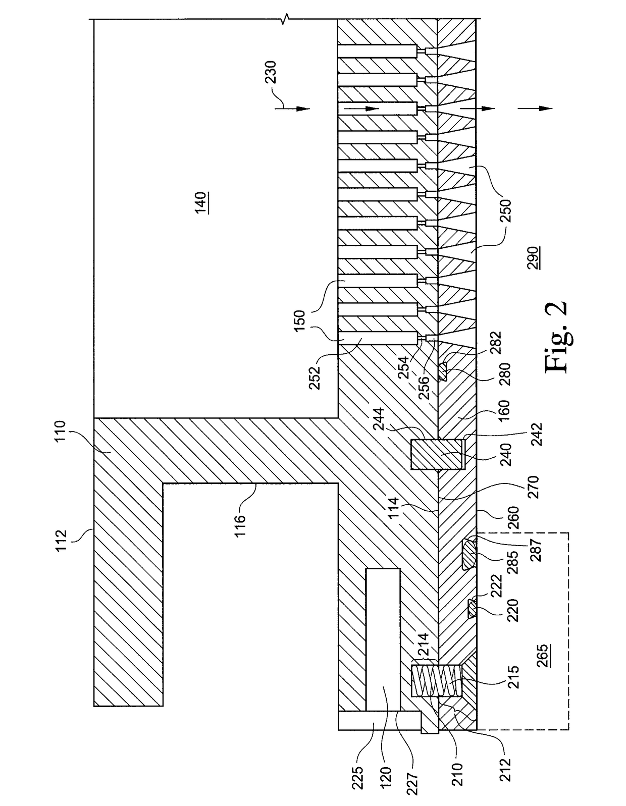
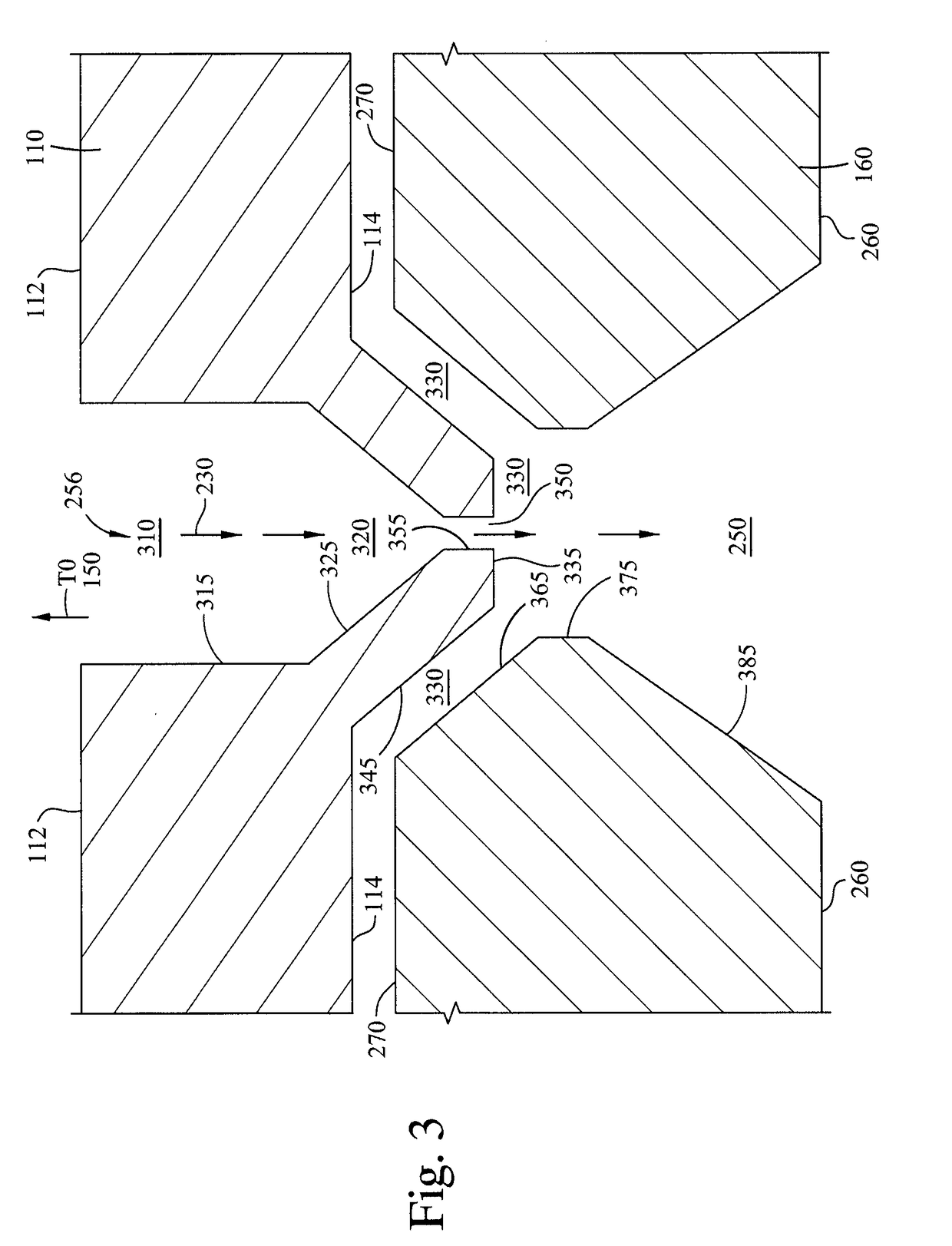
[0016]The disclosure described herein concerns a diffuser for use in a plasma processing chamber. As an exemplary embodiment thereof, a faceplate composed of a first place and a second plate, i.e., a multi-plate faceplate is described herein. However, the embodiments described herein can be applied to other gas diffuser apparatuses having gas flow openings extending therethrough, where the geometry of the openings prevents the placement of a proper protective coating on the surface of the opening, such as showerheads. By configuring the faceplate to incorporate a first plate and a second plate, and splitting the gas flow passages therebetween, a coating on the surface of the openings of the second plate of the multi-plate faceplate which are exposed to the process environment of a semiconductor process chamber can be uniformly applied thereto, even where the overall construct of the faceplate would result in a non-uniform coating application on the same portion of the opening in a s...


PUM


Abstract

Embodiments of the disclosure relate to a multi-plate faceplate having a first plate and a second plate. The first plate has a plurality of first plate openings. The second plate has a first surface, an opposed second surface and a plurality of second plate openings extending therethrough. The first surface is mechanically coupled to the first plate. A second plate opening has a conical portion configured to be fluidly coupled to a first plate opening and decreasing in cross-section in the depth direction thereof from the second surface. A surface of the conical portion is coated with a protective coating adjacent to the first and second surfaces. In another embodiment, the first plate has a protrusion extending therefrom into a recess formed inwardly of the first surface. The protrusion has a passage extending therethrough fluidly connected to the recess, which is fluidly connected to the second plate opening.

Description

BACKGROUNDField[0001]Embodiments of the disclosure generally relate to an apparatus for semiconductor device manufacturing. More particularly, the disclosure relates to a multi-plate faceplate for use within a semiconductor device processing chamber.Description of the Related Art[0002]Semiconductor device geometries have dramatically decreased in size since their introduction several decades ago. Increasing device densities have resulted in structural features having decreased spatial dimensions. Some manufacturing processes for fabricating semiconductor devices, such as plasma etching and plasma cleaning processes, expose a semiconductor substrate to a plasma in order to etch or clean the substrate. The plasma gas species may be highly corrosive, and therefore corrode processing chamber components and other surfaces that are exposed to the plasma.[0003]Some plasma processing chambers include a plasma generation section that provides energized species to a substrate processing porti...

Claims


Application Information

Patent Timeline
IPC IPC(8): H01J37/32B05B1/00B05B1/18
CPCH01J37/32449H01J37/32559H01J2237/002B05B1/18B05B1/005H01J37/32495H01J37/32853H01J37/32834H01L21/67017H01J37/3244H01J37/32513H01J2237/334H01J2237/335
Inventor SRIKANTAIAH, DEEPAK DODDABELAVANGALATULSHIBAGWALE, SHESHRAJ L.SINGH, SARAVJEETTAM, ALEXANDER
Owner APPLIED MATERIALS INC
Learn More