Interbody cage with spill-free biological material compartment

a biological material and cage technology, applied in the field of spinal stabilization cages, can solve the problems of difficult firmly packing the cavity, difficult to pack the cavity tightly, and inability to easily add additional bone grafting material

Active Publication Date: 2019-02-21
UNIV OF MARYLAND BALTIMORE
View PDF13 Cites 4 Cited by
  • Summary
  • Abstract
  • Description
  • Claims
  • Application Information

AI Technical Summary

Benefits of technology

[0006]In view of the above-mentioned exemplary problems with conventional and known interbody cages, the present application provides interbody cages having a spill-free, biological material compartment, and further provides associated methods for using the disclosed interbody cages.

Problems solved by technology

However, packing these central cavities tightly with such material can be difficult because the bone graft materials can fall out of the interbody cage while setting the interbody cage into place since, for example, force can be required to insert the interbody cage into the body.
One example of a disadvantage is that the top and bottom faces of the device are rigid, and thus the disclosed lordotic implant does not allow for maximum graft packing due to the rigidity of the cage.
Another disadvantage is that the sliding door of the lordotic implant is located on the rear face of the cage making it difficult to firmly pack the cavity since, for example, additional bone grafting material cannot be easily added to the cage after insertion into the body.
However, the cavity in the disclosed configuration is difficult to pack tightly.
Moreover, the surgeon inserting the disclosed cage in the body faces difficulty in determining the total amount of grafting material that should be inserted into the patient before the rear opening is closed.
Even further, packing the cage after insertion, can cause problems since the cage may migrate from the desired location.
If such migration occurs, a greater risk to the nerves and / or surrounding anatomy exists when packing the cage after insertion since these structures may be inadvertently damaged during the packing process.
Accordingly, the known techniques and, devices for spinal fusion procedures have a number of problems.

Method used


Image

  • Interbody cage with spill-free biological material compartment
  • Interbody cage with spill-free biological material compartment
  • Interbody cage with spill-free biological material compartment

Examples


Embodiment Construction

[0043]The interbody cages, for spinal stabilization and methods of the present application are now described by reference to the embodiments. The description provided herein is not intended to limit the scope of the claims, but to exemplify the variety encompassed by the present application. The embodiments are described more fully hereinafter with reference to the accompanying drawings in which like numerals represent like elements throughout the several figures, and in which example embodiments are shown. Embodiments of the claims may, however, be embodied in many different forms and should not be construed as limited to the embodiments set forth herein. The examples set forth herein are non-limiting examples and are merely examples among other possible examples.

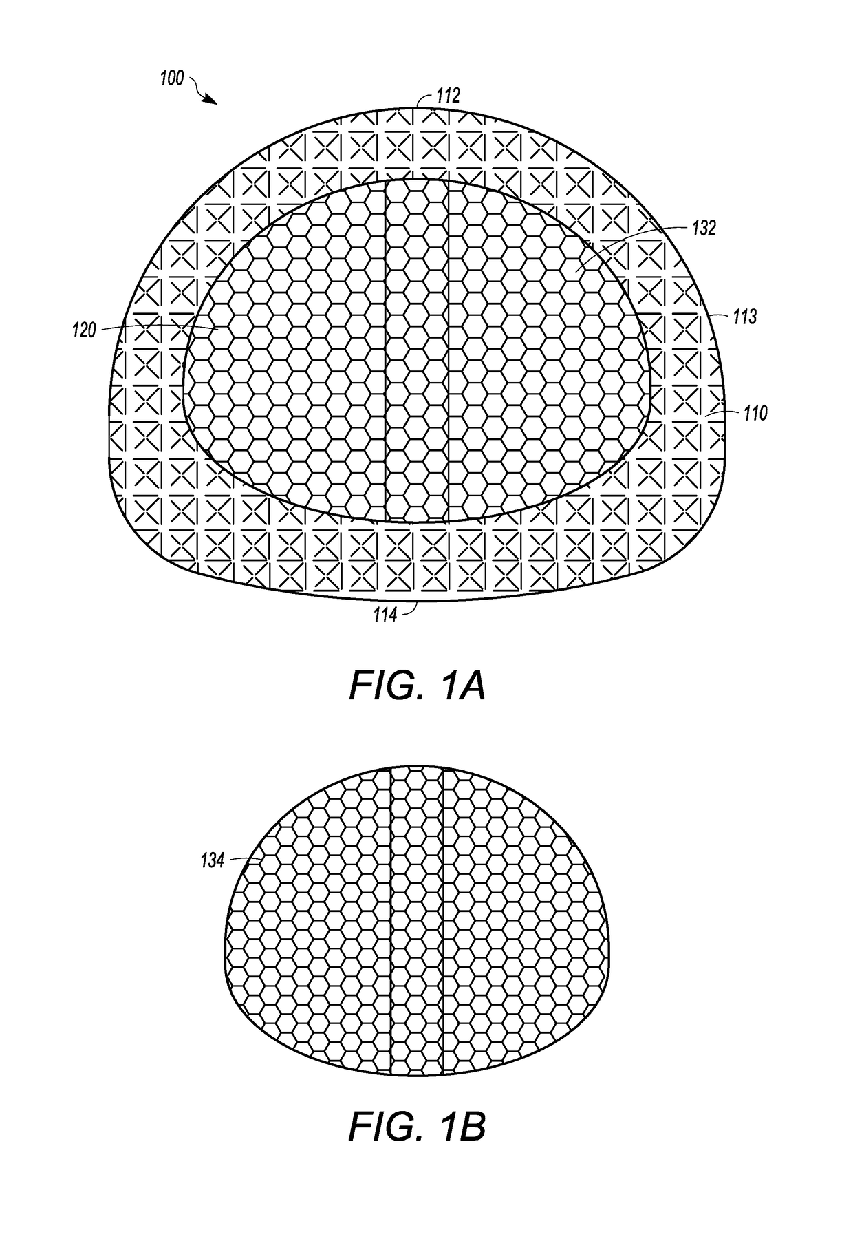
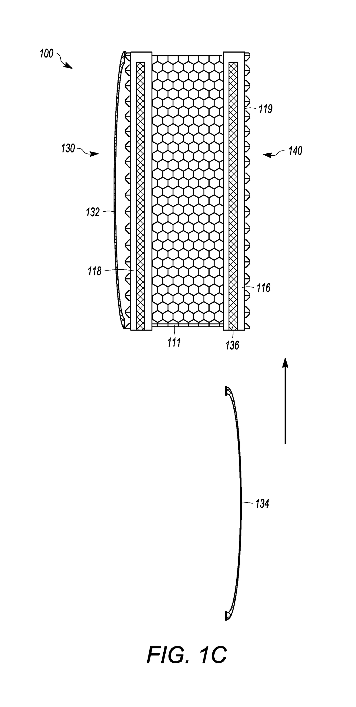
[0044]FIGS. 1A and 1C show an interbody cage 100 for spinal stabilization with a spill-free, biologic material compartment. The biological material can include, but is not limited to, bone grafting material selected from o...


PUM

PropertyMeasurementUnit
thicknessaaaaaaaaaa
thicknessaaaaaaaaaa
thicknessaaaaaaaaaa

Abstract

Interbody cages for spinal stabilization having a frame that surrounds a central compartment suitable for retaining biological material, such as bone graft material. The central, compartment acts as a spill-free bone and biologic compartment that allows a surgeon to introduce the interbody cage into the body in an effective manner without spilling the biological material. Methods for introducing the interbody cages are disclosed.

Description

TECHNICAL FIELD[0001]The present application generally relates to interbody cages for spinal stabilization. More specifically, the present application, relates to interbody cages for spinal stabilization with one or, more spill-free, biological material compartments.BACKGROUND[0002]During spinal fusion procedures, a solid bridge is typically formed between the two vertebral segments to limit movement in the section of the spine of the spinal fusion. A common technique for spinal fusion procedures involves the use of interbody cages, to fill the gap between the two segments in the spine that are being fused. The addition of bone graft material during the spinal fusion procedure can additionally provide a suitable foundation and environment that allows new bone growth and fuses the area of the procedure over time. Interbody cages can have central cavities that can be packed with bone graft materials. However, packing these central cavities tightly with such material can be difficult b...

Claims


Application Information

Patent Timeline
Patent Type & Authority Applications(United States)
IPC IPC(8): A61F2/44A61F2/30
CPCA61F2/441A61F2/4455A61F2/30771A61F2002/30784A61F2002/30904A61F2002/30471A61F2002/30476A61F2002/30589A61F2002/3093A61F2002/3092A61F2002/30522A61F2002/30581A61F2/30744A61F2/4465A61F2/447A61F2002/2835A61F2002/30387A61F2002/30578A61F2002/30909A61F2002/4629A61F2002/30593
Inventor SANSUR, CHARLESLUDWIG, STEVEN C.
Owner UNIV OF MARYLAND BALTIMORE
Why Eureka
Try Eureka