Pneumatic radial tire

Inactive Publication Date: 2019-02-28
SUMITOMO RUBBER IND LTD
View PDF0 Cites 1 Cited by
  • Summary
  • Abstract
  • Description
  • Claims
  • Application Information

AI Technical Summary

Benefits of technology

The present invention aims to provide a pneumatic radial tire that can improve the cornering performance of a four-wheeled vehicle while keeping its wet performance.

Problems solved by technology

First, in a four-wheeled vehicle of FF, a larger load tends to be applied to the front wheel tires than to the rear wheel tires.
Thereby, a tire with a large SAT results in relatively low equivalent CP.

Method used


Image

  • Pneumatic radial tire
  • Pneumatic radial tire
  • Pneumatic radial tire

Examples


working example (example)

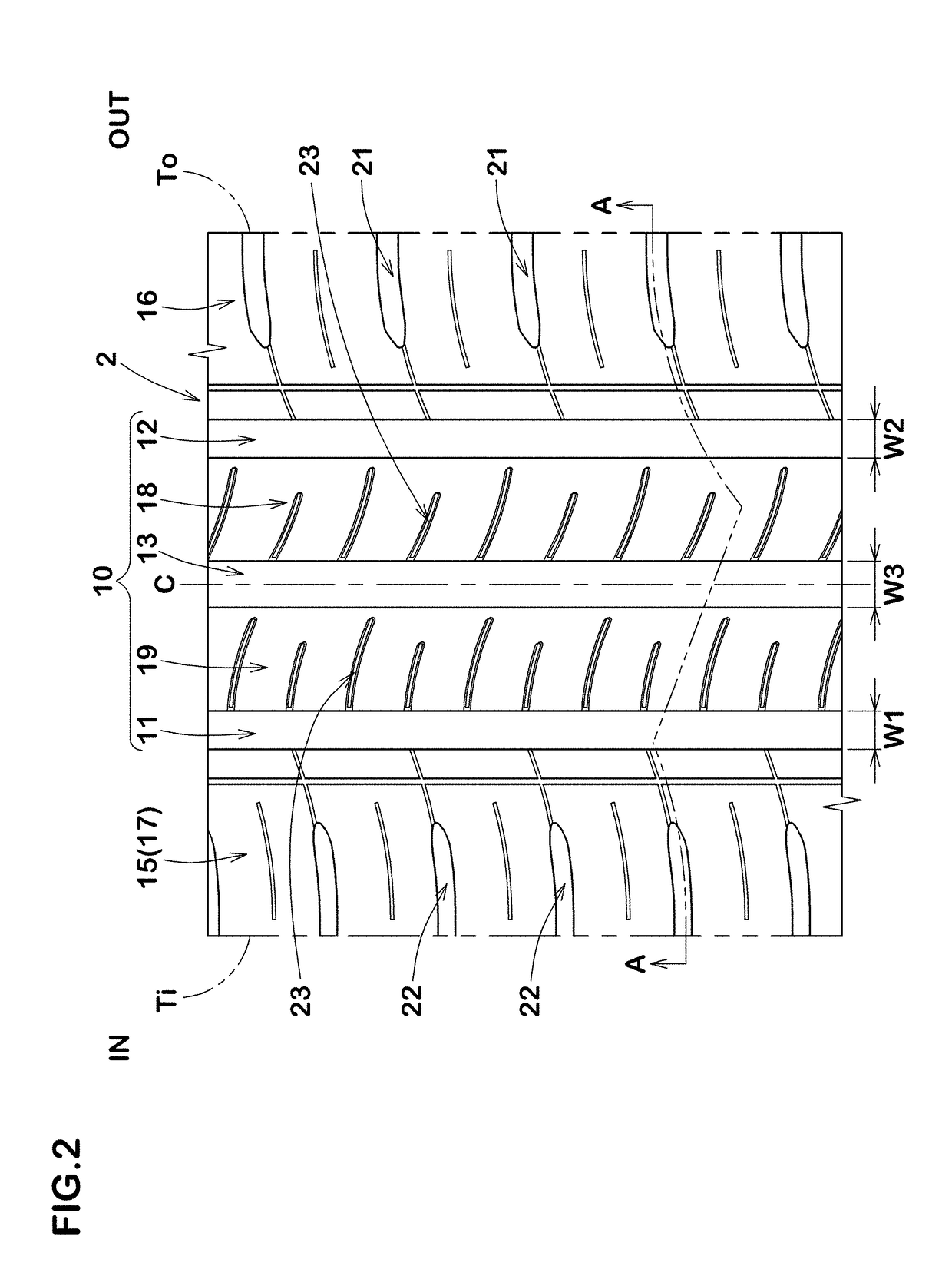
[0135]Tires of size 185 / 65R15 having the basic pattern shown in FIG. 2 were made by way of test according to the specifications listed in Table 1. As Reference, as shown in FIG. 14, tires in which the same number of the outer shoulder lateral grooves and the inner shoulder lateral grooves are provided and each of the middle land regions is provided with the lateral grooves each extending from respective one of the shoulder grooves toward the tire equator and terminating within the respective one of the middle land regions. Various tests were conducted for each of the test tires.

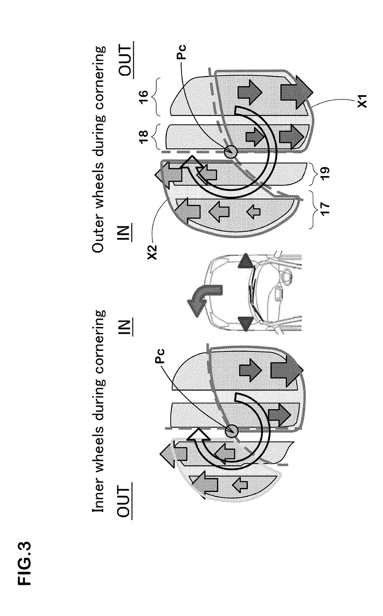
[0136]The test tires were mounted on four wheels of an FF passenger car with a displacement of 2000 cc under the following conditions, and then a driver cornered the test car on a dry road surface with the driver being the only member in the test car, and the cornering performance and the steering stability during the test drive was evaluated by the driver's feeling. The results are indicated by an evaluation...


PUM


Abstract

A pneumatic radial tire 1 for a passenger car includes a carcass 6, a belt layer 7, and a tread portion 2. The tread portion 2 includes outer and inner shoulder land regions 16 and 17 and outer and inner middle land regions 18 and 19. The outer shoulder land region 16 is provided with a plurality of outer shoulder lateral grooves 21. The inner shoulder land region 17 is provided with a plurality of inner shoulder lateral grooves 22. Number of the inner shoulder lateral grooves 22 is larger than number of the outer shoulder lateral grooves 21. The outer and inner middle land regions 18 and 19 are provided with a plurality of middle sipes 23 each extending from an edge on a side of an inner tread edge (Ti) of the respective land region toward an outer tread edge (To) and terminating within the respective land region.

Description

TECHNICAL FIELD[0001]The present invention relates to a pneumatic radial tire for a passenger car, and in particular to a pneumatic radial tire which is useful for improving cornering performance of a four-wheeled vehicle while maintaining wet performance.BACKGROUND ART[0002]FIG. 15 shows a time-series change in cornering motions of a general four-wheeled automobile having a steering mechanism on front wheels thereof. First, as in a state (A), when the steering wheel is operated by the driver during running straight, a slip angle is given to tires (b) of the front wheels, therefore, cornering force is generated at the tires (b) of the front wheels (state (B)). Here, the “slip angle” is an angle between the running direction of the vehicle body (c) and each of the tires (b). Further, the “cornering force” is a component of force applied in a lateral direction with respect to the running direction of frictional force generated on a ground contacting surface of each of the tires (b) wh...

Claims


Application Information

Patent Timeline
IPC IPC(8): B60C11/12B60C11/03
CPCB60C11/12B60C11/0304B60C2011/0339B60C11/01B60C11/1236B60C11/1272B60C2011/013B60C2011/1286B60C2011/0341B60C11/1204B60C2011/0374
Inventor IKEDA, RYOTANAKAYAMA, HIROYUKI
Owner SUMITOMO RUBBER IND LTD
Why Eureka
Try Eureka