Optical scanning device and image forming device having the same
- Summary
- Abstract
- Description
- Claims
- Application Information
AI Technical Summary
Benefits of technology
Problems solved by technology
Method used
Image
Examples
first embodiment
[0040]—Appearance of Image Forming Apparatus—
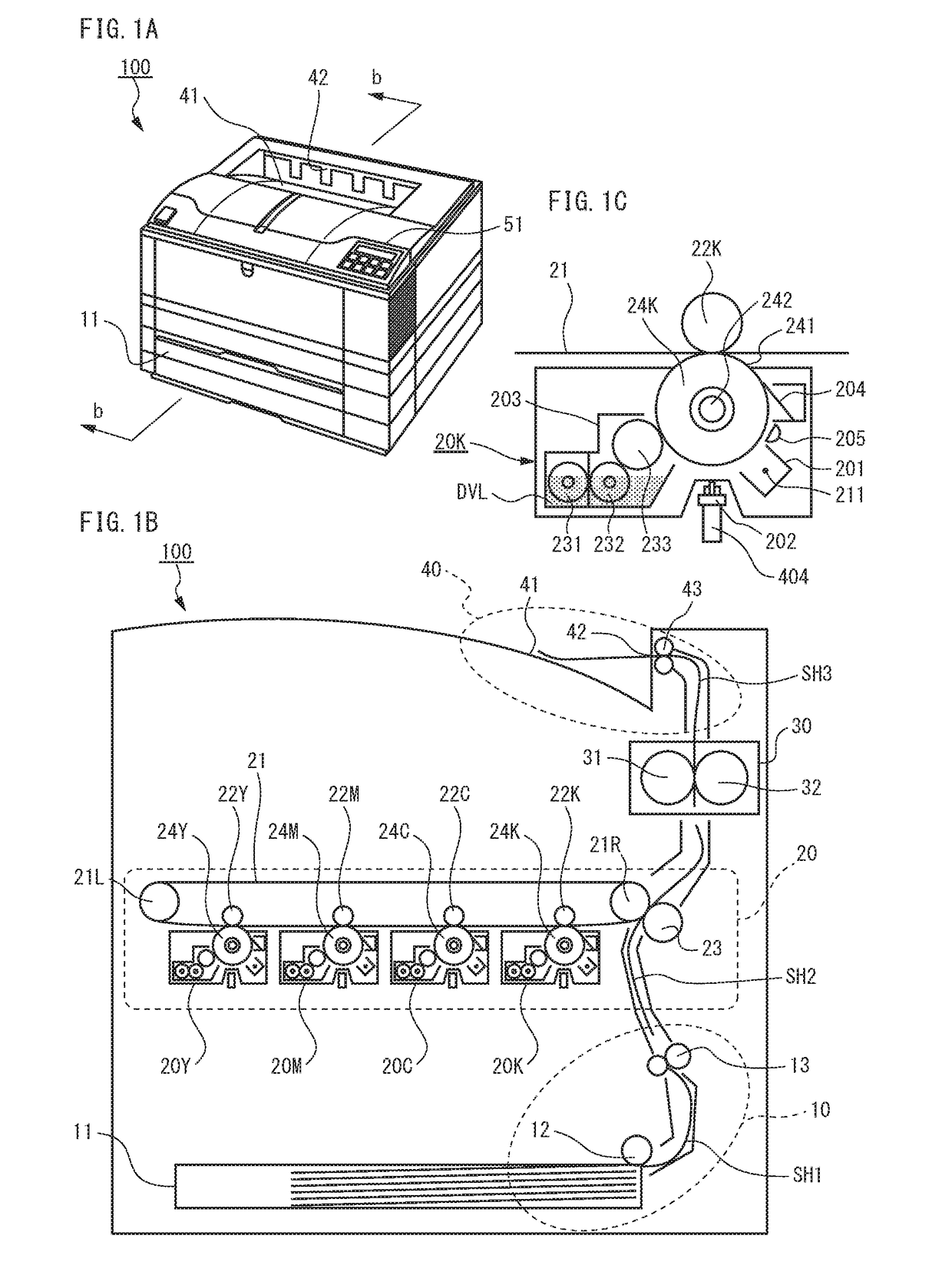
[0041]FIG. 1A is a perspective view of the appearance of an image forming apparatus 100 according to a first embodiment of the invention. This image forming apparatus 100 is a printer, which has, on the top of its body, an ejection tray 41 that stores sheets ejected from an ejection slot 42 located deep in the tray. The printer 100 also has, in front of the ejection tray 41, an operation panel 51 embedded, and in the bottom of its body, paper cassettes 11 attached to be able to slide out like drawers.
[0042]—Internal Configuration of Printer—
[0043]FIG. 1B is a schematic cross-sectional view of the printer 100 along the line b-b shown in FIG. 1A. The printer 100, which is an electrophotographic type capable of color printing, includes a feeder device 10, an imaging device 20, a fuser device 30, and an ejecting device 40.
[0044]The feeder device 10 first, with a pickup roller 12, separates each sheet SH1 from a stack of sheets stored in a pap...
second embodiment
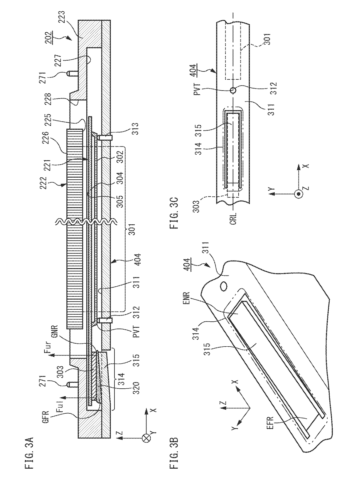
[0108]FIG. 8A is a longitudinal cross-sectional view of a print head 802 according to a second embodiment of the invention, and FIG. 8B is a longitudinal cross-sectional view of the print head 802 when its light source panel 221 and holder 223 are separated from a platform 804. This print head 802 has the same structure as the print head 202 according to the first embodiment, except for the structure of a portion of a reference face 811 of the platform 804 covered with heat conductor 820. This different structure will be explained below. Explanation about the other same structures can be found in the description of the first embodiment.
[0109]As shown in FIG. 8A, the reference face 811 of the platform 804 remains flat as a whole. In contrast to the reference face 311 in FIG. 3A, the portion of the reference face 811 covered with the heat conductor 820, together with other portions, substantially remains flat without the heat release section 314. On the other hand, the heat conductor ...
PUM
 Abstract
Description
Claims
Application Information
 - R&D
- Intellectual Property
- Life Sciences
- Materials
- Tech Scout
- Unparalleled Data Quality
- Higher Quality Content
- 60% Fewer Hallucinations
Browse by: Latest US Patents, China's latest patents, Technical Efficacy Thesaurus, Application Domain, Technology Topic, Popular Technical Reports.
© 2025 PatSnap. All rights reserved.Legal|Privacy policy|Modern Slavery Act Transparency Statement|Sitemap|About US| Contact US: help@patsnap.com


