Balance-spring stud-holder for a mechanical timepiece movement

Active Publication Date: 2019-02-28
ETA SA MFG HORLOGERE SUISSE
View PDF0 Cites 2 Cited by
  • Summary
  • Abstract
  • Description
  • Claims
  • Application Information

AI Technical Summary

Benefits of technology

[0019]That way, the balance-spring stud extracted from the notch is blocked in the abutment, which prevents the sprin

Problems solved by technology

The risk of breaking of t

Method used


Image

  • Balance-spring stud-holder for a mechanical timepiece movement
  • Balance-spring stud-holder for a mechanical timepiece movement
  • Balance-spring stud-holder for a mechanical timepiece movement

Examples


Example

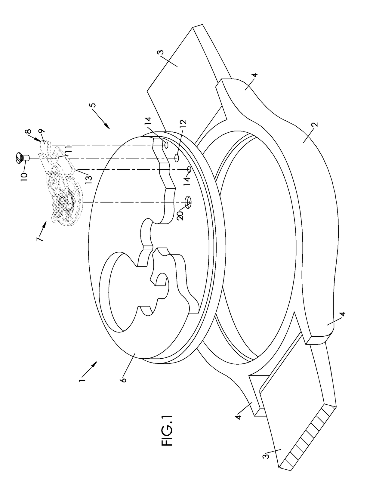
[0036]FIG. 1 shows a watch 1.

[0037]This watch 1 comprises a middle 2, which can in particular be made of metal (for example steel), or of a synthetic material (for example, a composite material comprising a polymer matrix filled with fibres, typically of carbon).

[0038]The watch 1 also comprises, for wearing on the wrist, a bracelet 3 which is fixed onto the middle 2 between horns 4 formed protruding therefrom.

[0039]The watch 1 also comprises a glass and a bottom (not represented), fixed onto the middle 2 on either side thereof.

[0040]The watch 1 comprises, finally, a timepiece movement 5, hereinafter simply called “movement”, which comprises a mainplate 6 intended to be housed in the middle 2 by being fixed thereto, for example by means of screws. The mainplate 6 forms a support for various mechanisms such as gear-train, adjustment mechanism, escapement, transmission, motion work, winding mechanism (list not exhaustive).

[0041]This timepiece movement 5 is mechanical, its motive energy...


PUM


Abstract

The invention relates to a balance-spring stud-holder for a mechanical timepiece movement, which comprises a pair of tabs, namely a front tab and a rear tab, jointly defining a notch, the tabs being arranged in such a way that a balance-spring stud can be held in the notch, wherein the rear tab of the balance-spring stud-holder comprises an extension which defines, beyond the notch, a bend forming a retaining abutment for the balance-spring stud after said balance-spring stud has been extracted from the notch.

Description

[0001]This application claims priority from European patent application No. 17188811.8 filed on Aug. 31, 2017, the entire disclosure of which is hereby incorporated herein by reference.TECHNICAL FIELD[0002]The invention deals with the field of watchmaking, and more particularly to the field of mechanical watchmaking, where the regulation of the motive energy is supplied by a spring oscillator. The invention relates, more specifically, to a balance-spring stud-holder for a mechanical movement.TECHNOLOGICAL BACKGROUND[0003]In most mechanical watches, the energy necessary for the rotation of the hands (for example hands indicating minutes and hours) is accumulated then dispensed by a balance-hairspring system, which comprises an inertia flywheel called balance, associated with a spring in the form of a spirally-wound tape, called hairspring.[0004]By an internal end, the hairspring is fixed onto an axis secured in rotation to the balance; by an outer end, the hairspring is fixed onto a ...

Claims


Application Information

Patent Timeline
IPC IPC(8): G04B18/06G04B17/06
CPCG04B18/06G04B17/063G04B17/066G04B17/26G04B17/325G04B18/02
Inventor CHRISTAN, JULIENCONUS, THIERRY
Owner ETA SA MFG HORLOGERE SUISSE
Why Eureka
Try Eureka