
Method and apparatus of digital beamforming for a radar system

Active Publication Date: 2019-02-28
RAYTHEON CO
View PDF7 Cites 7 Cited by
  • Summary
  • Abstract
  • Description
  • Claims
  • Application Information

AI Technical Summary

Benefits of technology

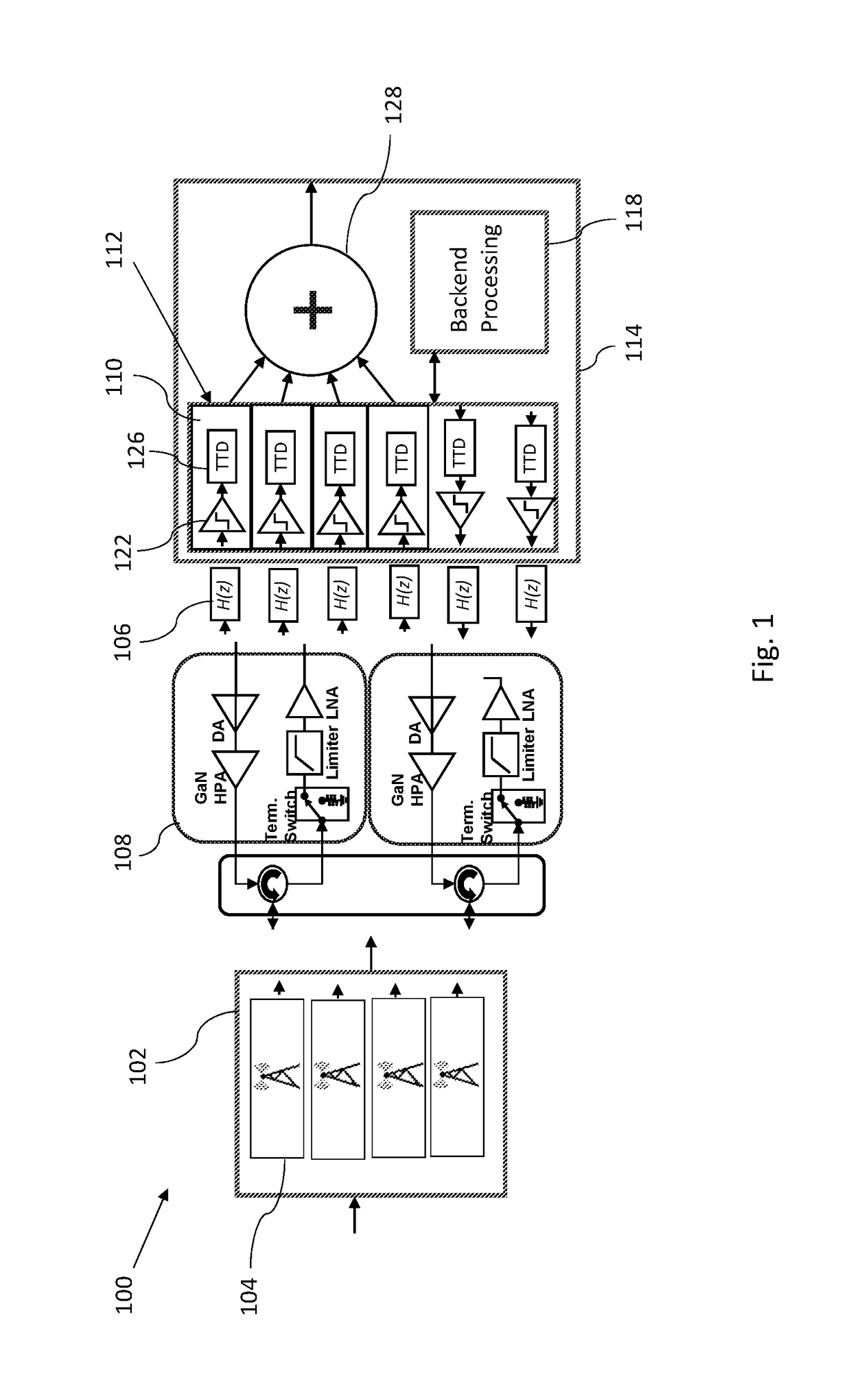
The patent is about a new system and method for digital beamforming that is affordable, efficient, and accurate. The system uses a fully digital, wideband approach that is driven directly within a digital signal processing chip, such as a FPGA, which requires very few external components. This technology may be useful for a variety of applications where efficient and precise digital beamforming is needed.

Problems solved by technology

Further, available designs often include Analog-to-Digital Converters (ADC) that are separate from the FPGA, as FPGAs have limited functions when it comes to analog capabilities.
These systems also tend to require numerous analog components such as filters, mixers, amplifiers, and the like, thereby increasing SWaP concerns.
The integration of all these components together in a small form factor for a low cost is a challenge.
Fully digital PAR programs can cost many millions of dollars and optimal SWaP modules capable of wide bandwidths (e.g. ESM modes) are not available.

Method used


Image

  • Method and apparatus of digital beamforming for a radar system
  • Method and apparatus of digital beamforming for a radar system

Examples


Embodiment Construction

[0012]The subject technology overcomes many of the prior art problems associated with digital beamforming. The advantages, and other features of the systems and methods disclosed herein, will become more readily apparent to those having ordinary skill in the art from the following detailed description of certain preferred embodiments taken in conjunction with the drawings which set forth representative embodiments of the present invention. Like reference numerals are used herein to denote like parts. Further, words denoting orientation such as “upper”, “lower”, “distal”, and “proximate” are merely used to help describe the location of components with respect to one another. For example, an “upper” surface of a part is merely meant to describe a surface that is separate from the “lower” surface of that same part. No words denoting orientation are used to describe an absolute orientation (i.e. where an “upper” part must always be at a higher elevation).

[0013]It is to be understood tha...


PUM


Abstract

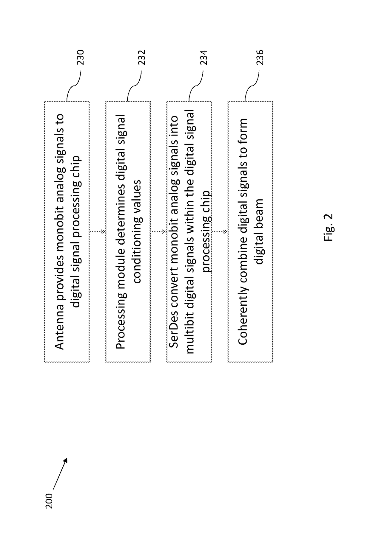
A system and method of digital beamforming for a monobit phased array radar system includes providing a plurality of monobit analog signals received by at least one antenna to at least one field programmable gate array (FPGA). A plurality of monobit SerDes transceivers within the FPGA convert the plurality of monobit analog signals into a plurality of multibit digital signals, each of the multibit digital signals being modified according to a digital signal conditioning value to calibrate, phase align, and synchronize the digital signals. A digital beam is formed by coherently combining the plurality of digital signals within the FPGA.

Description

FIELD OF THE INVENTION[0001]The subject disclosure relates to radar systems and more particularly to systems and methods of digital beamforming for radar systems.BACKGROUND OF THE INVENTION[0002]Current digital phase array systems can cost upwards of $10,000 per channel. Design choice decisions often include balancing trade-offs between size, weight and power (SWaP) and performance, among other things. Field programmable gate array (FPGA) devices are used to provide advantages for digital-based functions. Further, available designs often include Analog-to-Digital Converters (ADC) that are separate from the FPGA, as FPGAs have limited functions when it comes to analog capabilities. This results in numerous external multiple bit ADCs connecting with the FPGA. These systems also tend to require numerous analog components such as filters, mixers, amplifiers, and the like, thereby increasing SWaP concerns.[0003]Additionally, certain phase array systems, such as phased array radar (PAR), ...

Claims


Application Information

Patent Timeline
IPC IPC(8): H01Q3/38H01Q21/22G01S13/02
CPCH01Q3/38G01S2013/0254G01S13/0209H01Q21/22G01S7/032G01S7/4026H01Q3/2605H01Q3/2682
Inventor THOMPSON, DANIELMARR, HARRY B.ROBINSON, IANCALDWELL, JEFFREY
Owner RAYTHEON CO
Learn More