Electromagnetically moving device
a technology of moving devices and magnets, applied in the direction of magnets, cores/yokes, magnetic bodies, etc., can solve the problems of power failure, not avoiding enlargement, and increasing the cost of the devi
- Summary
- Abstract
- Description
- Claims
- Application Information
AI Technical Summary
Benefits of technology
Problems solved by technology
Method used
Image

Examples
embodiment 1
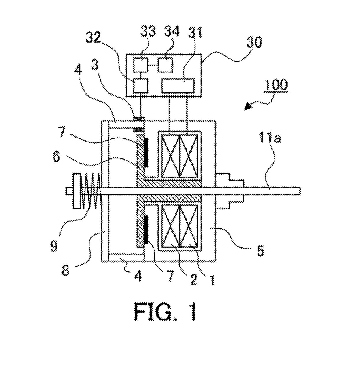
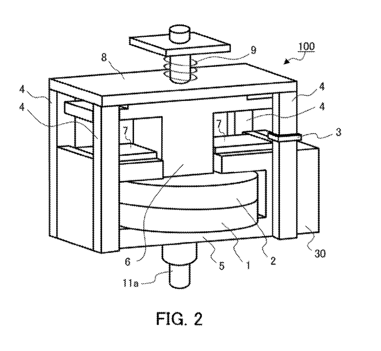
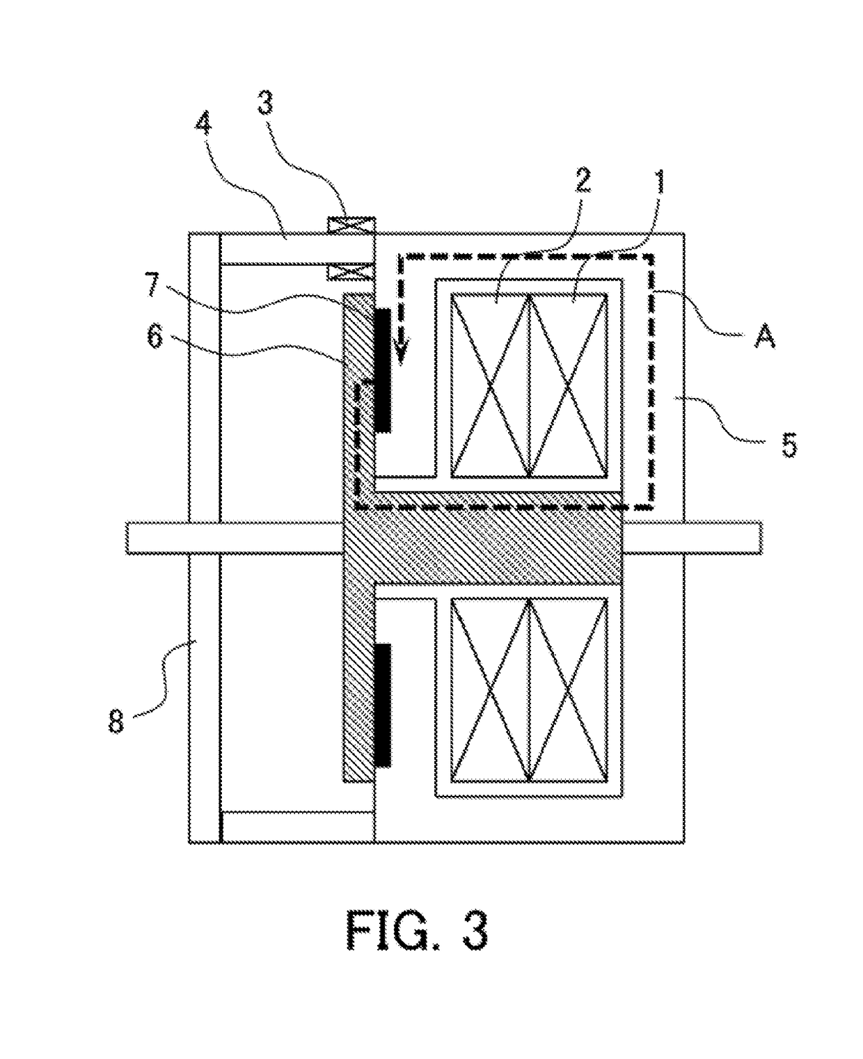
[0022]FIG. 1 is a cross-sectional view showing a configuration of an electromagnetically moving device 100 according to Embodiment 1 of the application, and FIG. 2 is a perspective view thereof. As shown in FIG. 1 and FIG. 2, the electromagnetically moving device 100 is configured with an opening coil 1, a turn-on coil 2, a magnetic-flux variation measuring unit 3, support columns 4, a stationary core 5, a movable core 6, permanent magnets 7, a stopper plate 8, an opening spring 9, a driving shaft 11a and a measurement control section 30.
[0023]In the electromagnetically moving device 100, the stationary core 5 is placed so as to surround the opening coil 1 and the turn-on coil 2 as drive coils. The movable core 6 is provided in a releasably attachable manner to the stationary core 5, and the permanent magnets 7 are each placed on a surface where the stationary core and the movable core 6 are attached to each other. Further, the movable core 6 is configured with the driving shaft 11a...
embodiment 2
[0048]In Embodiment 1, the description has been made about the case where the magnetic-flux variation measuring unit 3 is placed on one of the four support columns 4, whereas in Embodiment 2, description will be made about a case where it is placed on each of plural support columns.
[0049]FIG. 8 is a cross-sectional view showing a configuration of an electromagnetically moving device 101 according to Embodiment 2 of the application, and FIG. 9 is a perspective view thereof. As shown in FIG. 8 and FIG. 9, in the electromagnetically moving device 101, two magnetic-flux variation measuring units 3a, 3b are placed on two of the four support columns each existing outside the closed magnetic path formed by the magnetic-flux flow caused by the permanent magnet 7. The other configuration of the electromagnetically moving device 101 is the same as that of the electromagnetically moving device 100 of Embodiment 1, so that the same reference numerals are given to the equivalent parts and descri...
embodiment 3
[0057]In Embodiment 1 and Embodiment 2, the description has been made about the case where the behavior estimation unit 32 refers to the normal values (reference values) measured at the delivery inspection, etc., whereas in Embodiment 3, description will be made about a case where the behavior estimation unit 32 does not use such data measured at the delivery inspection, etc.
[0058]In the case where, for some reason, an electronic circuit included in the measurement control section 30 is changed, or an element in the magnetic-flux variation measuring unit 3 or a movable-part component in the switch / breaker is replaced, there is a likelihood that the device is recognized as another individual than that at the time of delivery, so that the previous data may affect the status determination result. Accordingly, resetting of the reference values is required. In the following, operations of the behavior estimation unit 32 when only one magnetic-flux variation measuring unit 3 is provided w...
PUM
| Property | Measurement | Unit |
|---|---|---|
| magnetic | aaaaa | aaaaa |
| magnetic-flux | aaaaa | aaaaa |
| magnetic force | aaaaa | aaaaa |
Abstract
Description
Claims
Application Information
 - R&D
- Intellectual Property
- Life Sciences
- Materials
- Tech Scout
- Unparalleled Data Quality
- Higher Quality Content
- 60% Fewer Hallucinations
Browse by: Latest US Patents, China's latest patents, Technical Efficacy Thesaurus, Application Domain, Technology Topic, Popular Technical Reports.
© 2025 PatSnap. All rights reserved.Legal|Privacy policy|Modern Slavery Act Transparency Statement|Sitemap|About US| Contact US: help@patsnap.com