Low resistance coil structure for high speed writer

a low resistance coil and high speed technology, applied in the field of magnetic write heads, can solve the problems of reducing the cross-section of the conductor and the johnson thermal power noise, and johnson thermal power noise, and achieving the effect of reducing the cross-section and distance to the air bearing surfa

Inactive Publication Date: 2001-12-25
WESTERN DIGITAL TECH INC
View PDF15 Cites 167 Cited by
  • Summary
  • Abstract
  • Description
  • Claims
  • Application Information

AI Technical Summary

Benefits of technology

The preferred embodiment of the present invention provides reduced coil resistance thereby reducing Johnson Thermal Noise and power dissipation. It also allows for reduced yoke length and reduced stack height while providing low apex angles thereby expanding and improving yoke material deposition to improve head response and operational frequency.

Problems solved by technology

Reducing conductor cross-section and distance to the air bearing surface, however, presents problems.
Decreasing conductor size, for example, increases the resistance of the conductor winding causing a potential problem with Johnson Thermal Power Noise.
As the resistance and operating frequency increase, Johnson Thermal Power Noise poses a greater problem.
Conventional thin film head design, however, limits the type of materials available for use.
High moment materials generally are deposited by vacuum deposition and are prone to cracking when deposited over steep surfaces.
These steep angles limit the deposition methods and type of materials available for forming the upper pole structure, thus presenting impediments to increasing the operating frequency of the write head.

Method used


Image

  • Low resistance coil structure for high speed writer
  • Low resistance coil structure for high speed writer
  • Low resistance coil structure for high speed writer

Examples


Embodiment Construction
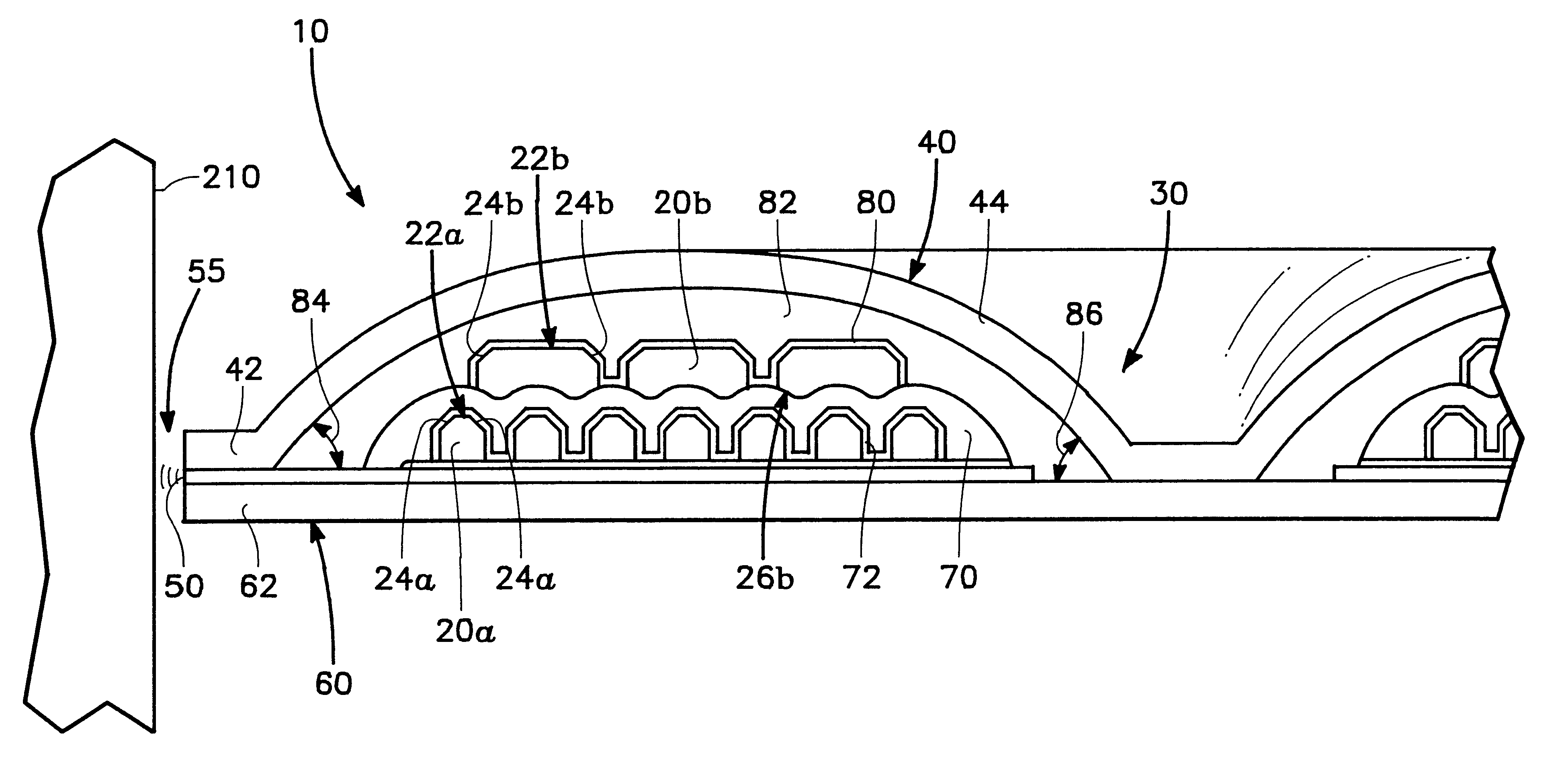
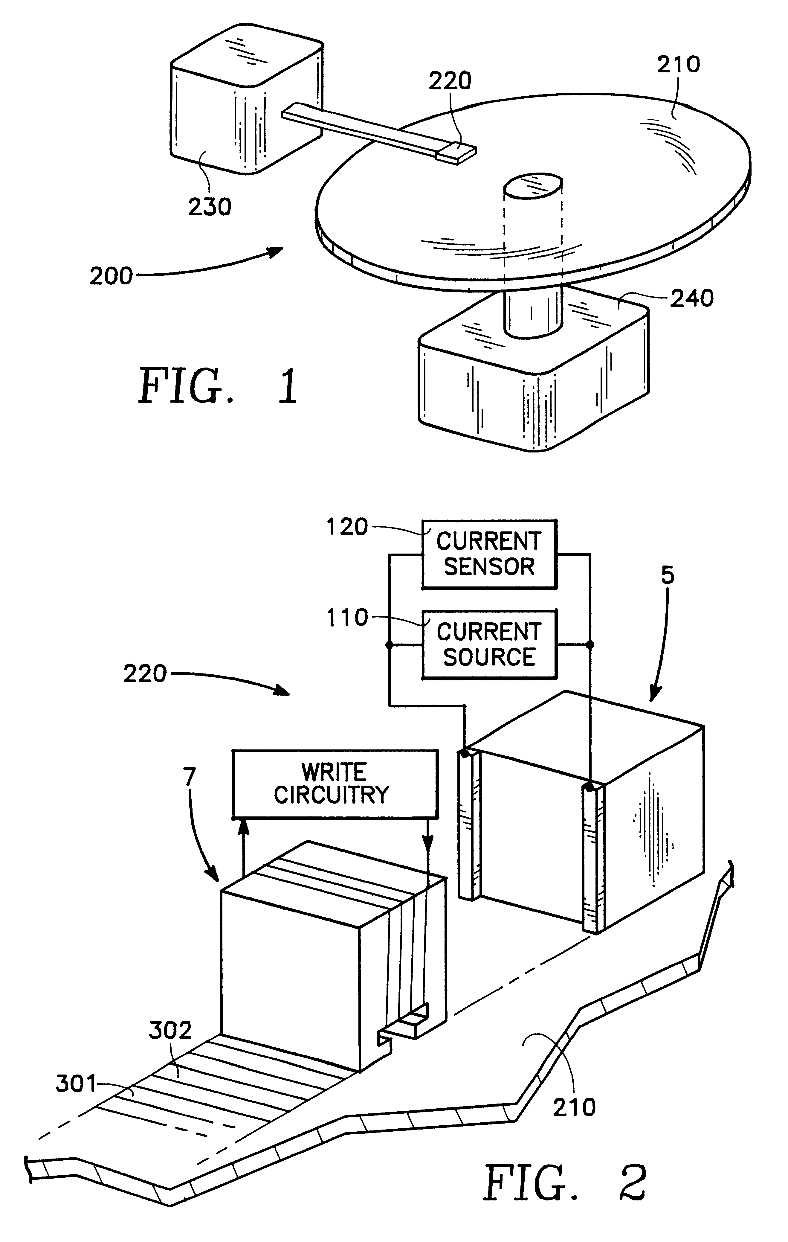
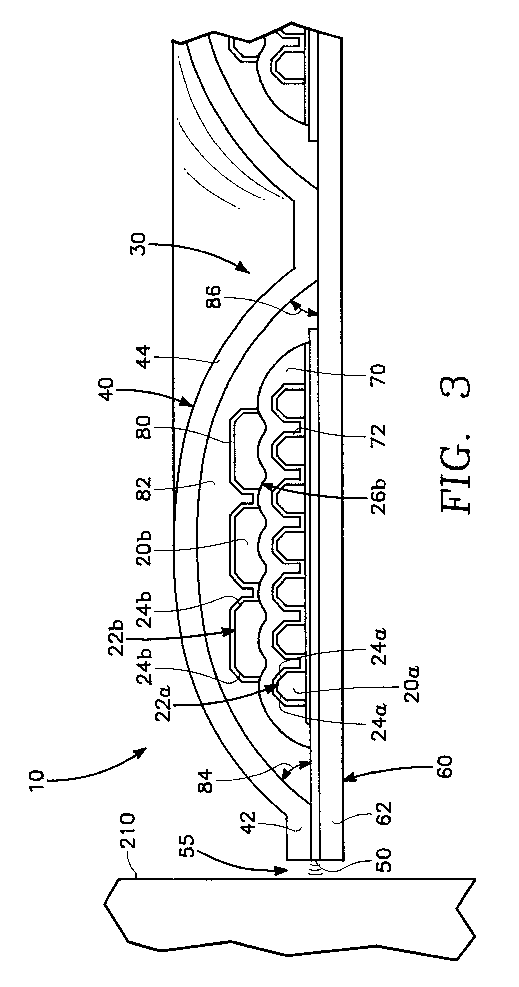
FIGS. 1-3

FIG. 1 shows the thin film write head of the present invention embodied in a disk type magnetic data storage and retrieval apparatus 200. The write head of the present invention is located within a merged head assembly 220 which rides above a magnetic storage media 210, depicted in FIG. 1 as a rotatable hard disk type storage media. The hard disk 210 is coupled to a motor 240 to provide rotation of the disk relative to the head assembly 220. An actuating means 230 may be used to position the head assembly 220 above the surface of the media 210 to read and write data in the form of magnetic bits from and to the media 210. The data storage and retrieval apparatus 200, typically has several hard disks 210 and several corresponding head assemblies 220.

FIG. 2 shows a simplified functional illustration of the head assembly 220. Merged head assemblies 220 are formed having a write head 7, used to write or set the magnetization of bits 301, 302 on the media 210, while a read head 5...


PUM

PropertyMeasurementUnit
thickaaaaaaaaaa
apex anglesaaaaaaaaaa

Abstract

The present invention provides a thin film write head having an upper and lower pole structures and conductor turns forming a winding for generating magnetic flux. The conductor is formed with a non-planar top surface. The winding of the present invention may be formed of lower and upper turns. The upper turns may be formed with a non-planar top surface, a non-planar bottom surface, or both. It is preferred that the bottom surface of the upper conductor turns be coherent with the non-planar top surface of the lower conductor turns. The non-planar top surface may be formed by removing corners formed during deposition between a generally planar top surface and abutting side walls. The corners may be removed by ion milling to form the non-planar top surface. The conductor may be copper with the non-planar top surface having sloping facets. The thin film write head of the present invention may be utilized to provide an improved data storage and retrieval apparatus. The preferred embodiment provides reduced coil resistance thereby reducing Johnson Thermal Noise and power dissipation. It also allows for reduced yoke length and reduced stack height while providing low apex angles to expand and improve yoke material deposition thereby improving head response and operational frequency.

Description

1. Field of the InventionThe present invention relates to the field of magnetic write heads.2. Description of Related ArtData is stored on magnetic media by writing to the magnetic media using a write head. Magnetic media can be formed in any number of ways, such as tape, floppy diskette, and hard disk. Writing involves storing a data bit by utilizing magnetic flux to set the magnetic moment of a particular bit or area on the magnetic media. As data density is improved by placing bits closer together, larger magnetic flux is required to set the bits to prevent them from inadvertently being changed by adjacent bits, or by stray magnetic flux.In addition to improving density, the rate or frequency that data is stored to the media is an important measure of the operational performance of the write head. The operating frequency is determined, in part, by the structures and materials of the write head.Thin film heads commonly employ separate write and read heads and are typically formed ...

Claims


Application Information

Patent Timeline
Patent Type & Authority Patents(United States)
IPC IPC(8): G11B5/31
CPCG11B5/3123G11B5/82
Inventor ROSE, CHUCKSHI, ZHUPEIKNAPP, KENNETH E.
Owner WESTERN DIGITAL TECH INC
Why Eureka
Try Eureka