Coil component

a technology of coil components and components, applied in the direction of transformer/inductance details, inductances with magnetic cores, inductances, etc., can solve the problems of reducing the performance of other components used, generating a large amount of heat when used, and improving heat dissipation characteristics, so as to reduce the resistance of the coil electrode, reduce the performance of other components, and improve the heat dissipation characteristics of such coil components

Active Publication Date: 2017-08-17
MURATA MFG CO LTD
View PDF1 Cites 1 Cited by
  • Summary
  • Abstract
  • Description
  • Claims
  • Application Information

AI Technical Summary

Benefits of technology

[0009]There are some coil components of this type whose specification requires the flow of a large electric current through the coil electrode. Such coil components generate a large amount of heat when they are used. The generation of heat by such coil components may reduce the performance of other components that are used with such coil components. Therefore, improving heat dissipation characteristics of such coil components and reducing the resistance of the coil electrode are issues. In the existing coil component 100, these issues may be solved by increasing the diameter of each columnar conductor 102c. However, in the case of a toroidal coil whose winding axis circular, space that is provided at an inner side of the circle is limited. Therefore, when the diameter of the inner columnar conductors 102c at the inner side is increased, the number of turns of the coil electrode 102 is reduced. When the number of turns of the coil electrode 102 is reduced, the inductance value is reduced and, thus, the characteristics of the coil electrode 102 are reduced. Therefore, there is a demand for a technology that can reduce the resistance of coil electrodes and improve the heat dissipation characteristics without reducing the coil characteristics.
[0010]In view of the above-described problems, it is an object of the present disclosure to a provide a coil component that allows the resistance of a coil electrode to be reduced and heat dissipation characteristics to be improved without reducing the number of turns of the coil electrode, the coil component including an insulating layer in which an annular coil core is embedded and the coil electrode which is wound around the coil core.

Problems solved by technology

Such coil components generate a large amount of heat when they are used.
The generation of heat by such coil components may reduce the performance of other components that are used with such coil components.
Therefore, improving heat dissipation characteristics of such coil components and reducing the resistance of the coil electrode are issues.
However, in the case of a toroidal coil whose winding axis circular, space that is provided at an inner side of the circle is limited.

Method used


Image

  • Coil component
  • Coil component
  • Coil component

Examples


first embodiment

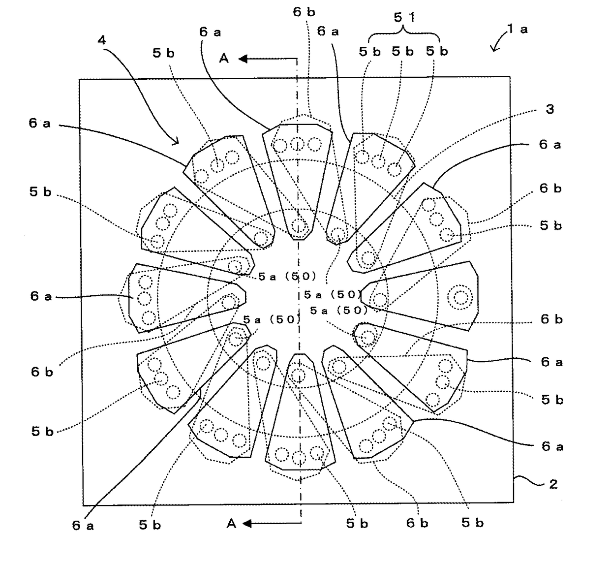
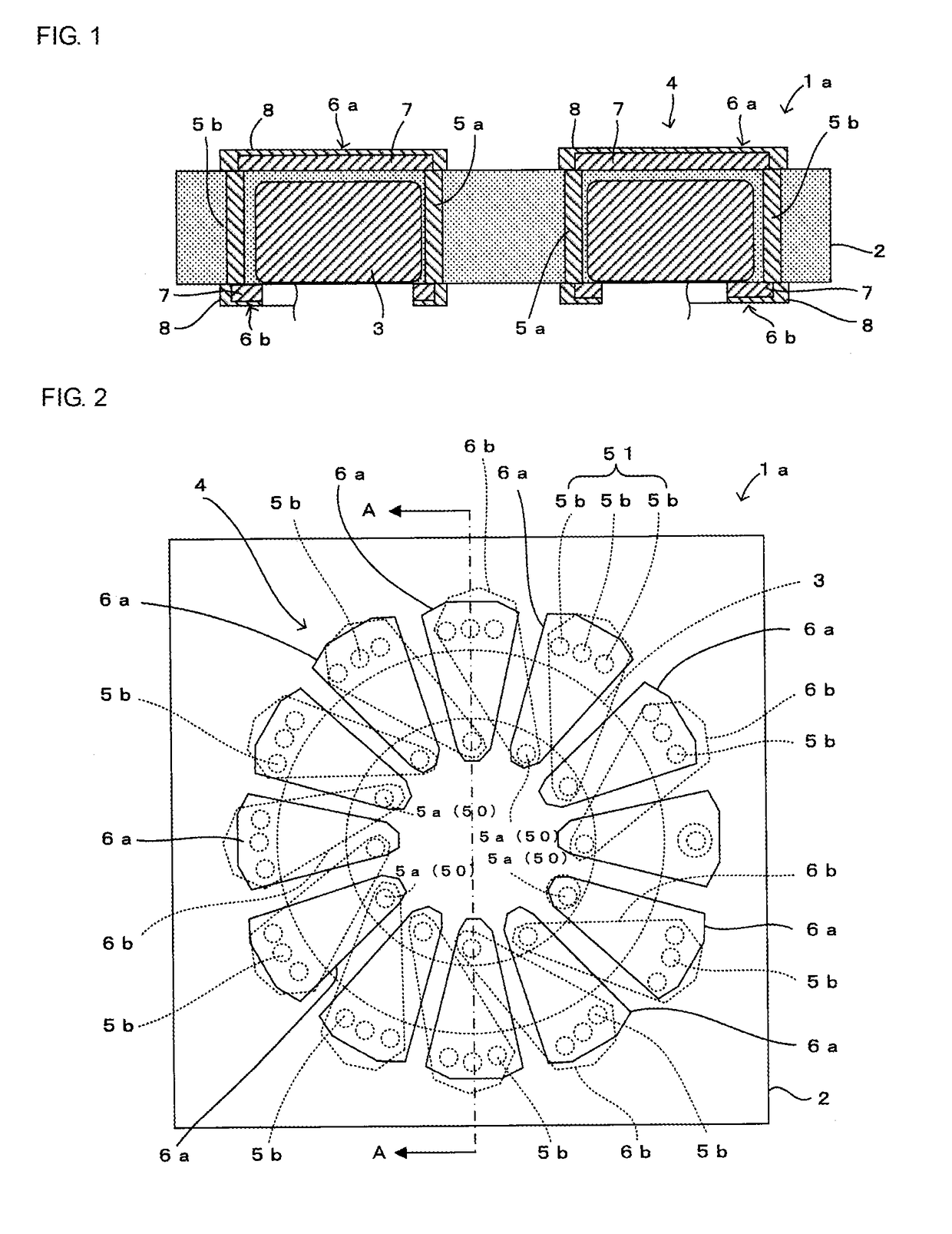
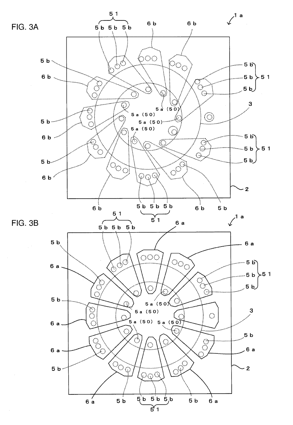
[0032]A coil component 1a according to a first embodiment of the present disclosure is described with reference to FIGS. 1 to 3B. FIG. 1 is a sectional view of the coil component 1a. FIG. 2 is a plan view of the coil component 1a. FIGS. 3A and 3B illustrate wiring patterns 6a and 6b. FIG. 3A is a plan view of the coil component 1a without the upper wiring patterns 6a. FIG. 3B is a plan view of the coil component 1a without the lower wiring patterns 6b. FIG. 1 is a sectional view taken along arrow A-A in FIG. 2. In FIG. 3A, input and output wires that are connected to end portions of a coil electrode 4 are not shown.

[0033]As shown in FIGS. 1 to 3B, the coil component 1a according to the embodiment includes an insulating layer 2 in which a coil core 3 is embedded and a coil electrode 4 which is wound around the coil core 3; and is mounted on an electronic device such as a cellular phone that uses high-frequency signals.

[0034]The insulating layer 2 is made of, for example, a resin such...

second embodiment

[0059]A coil component 1b according to a second embodiment of the present disclosure is described with reference to FIG. 4. FIG. 4 is a plan view of the coil component 1b without lower wiring patterns 6b, and corresponds to FIG. 3B.

[0060]The coil component 1b according to this embodiment differs from the coil component 1a according to the first embodiment described with reference to FIGS. 1 to 3B as follows. That is, as shown in FIG. 4, the coil component 1b differs therefrom in the number of outer metal pins 5b that make up each outer conductor 51, and in that the outer metal pins 5b are thicker than inner metal pins 5a (excluding the metal pin for external connection). The other structural features are the same as those of the coil component 1a according to the first embodiment. Therefore, such other structural features are given the same reference numerals, and are not described.

[0061]In this case, each outer conductor 51 includes two outer metal pins 5b, and is thicker than the ...

third embodiment

[0063]A coil component 1c according to a third embodiment of the present disclosure is described with reference to FIG. 5. FIG. 5 is a plan view of the coil component 1c without lower wiring patterns 6b, and corresponds to FIG. 3B.

[0064]The coil component 1c according to this embodiment differs from the coil component 1a according to the first embodiment described with reference to FIGS. 1 to 3B as follows. That is, as shown in FIG. 5, the coil component 1c differs therefrom in that inner metal pins 5a are thicker than outer metal pins 5b. The other structural features are the same as those of the coil component 1a according to the first embodiment. Therefore, such other structural features are given the same reference numerals, and are not described.

[0065]In this case, the outer metal pins 5b have the same thickness and the same length, and the inner metal pins 5a have the same thickness and the same length. Each inner metal pin 5a is thicker than each outer metal pin 5b. In additi...


PUM

PropertyMeasurementUnit
thicknessaaaaaaaaaa
frequencyaaaaaaaaaa
magneticaaaaaaaaaa

Abstract

A coil electrode of a coil component includes a plurality of lower wiring patterns arranged on a lower surface of an insulating layer; a plurality of upper wiring patterns arranged on an upper surface of the insulating layer; a plurality of inner conductors disposed at an inner peripheral side of the coil core, each inner conductor connecting one end of the corresponding one of the lower wiring patterns and one end of a corresponding one of the upper wiring patterns forming the pair with the lower wiring pattern; and a plurality of outer conductors disposed at an outer peripheral side of the coil core, each outer conductor connecting the other end of the corresponding one of the lower wiring patterns and the other end of the corresponding one of the upper wiring patterns adjacent to an upper wiring pattern forming the pair with the lower wiring pattern.

Description

[0001]This is a continuation of International Application No. PCT / JP2015 / 082077 filed on Nov. 16, 2015 which claims priority from Japanese Patent Application No. 2014-234936 filed on Nov. 19, 2014. The contents of these applications are incorporated herein by reference in their entireties.BACKGROUND OF THE DISCLOSURE[0002]Field of the Disclosure[0003]The present disclosure relates to a coil component including an insulating layer and a coil electrode, a coil core being embedded in the insulating layer and the coil electrode being wound around the coil core.[0004]Description of the Related Art[0005]In an electronic device that uses high-frequency signals, a coil component is sometimes used for preventing noise. This type of coil component includes a coil core that is made of, for example, a magnetic material, and a coil electrode that is wound around the coil core. Here, the coil core is often manually wound around the coil electrode. Eliminating such a manual operation is an issue i...

Claims


Application Information

Patent Timeline
Patent Type & Authority Applications(United States)
IPC IPC(8): H01F27/32H01F27/28
CPCH01F27/2804H01F27/323H01F17/06H01F41/08H01F17/0013H01F41/043
Inventor OTSUBO, YOSHIHITOKUROBE, JUNJINISHIDE, MITSUYOSHI
Owner MURATA MFG CO LTD
Why Eureka
Try Eureka