Thin film magnetic head having recording coil and method of forming recording coil

a technology of thin film magnetic head and recording coil, which is applied in the direction of magnetic recording head, data recording, instruments, etc., can solve the problems of damage to the recording medium and the damage to the thin film magnetic head itself, and achieve the effect of reducing the resistance of the coil

Inactive Publication Date: 2007-05-31
TDK CORPARATION
View PDF0 Cites 1 Cited by
  • Summary
  • Abstract
  • Description
  • Claims
  • Application Information

AI Technical Summary

Benefits of technology

[0015] In one embodiment, since the recording coil has end portions in the coil width direction that are thicker than the central portion by plating, it is possible to sufficiently achieve a cross-sectional area of the coil in a complete state even though both end portions of the upper surface of the recording coil is cut in the milling process after the plating is formed. Accordingly, a thin film magnetic head that has a recording coil and a method of forming a recording coil that are capable of reducing coil resistance are obtained.

Problems solved by technology

The protrusion may damage the recording medium, or the thin film magnetic head itself may be damaged.

Method used


Image

  • Thin film magnetic head having recording coil and method of forming recording coil
  • Thin film magnetic head having recording coil and method of forming recording coil
  • Thin film magnetic head having recording coil and method of forming recording coil

Examples


Embodiment Construction

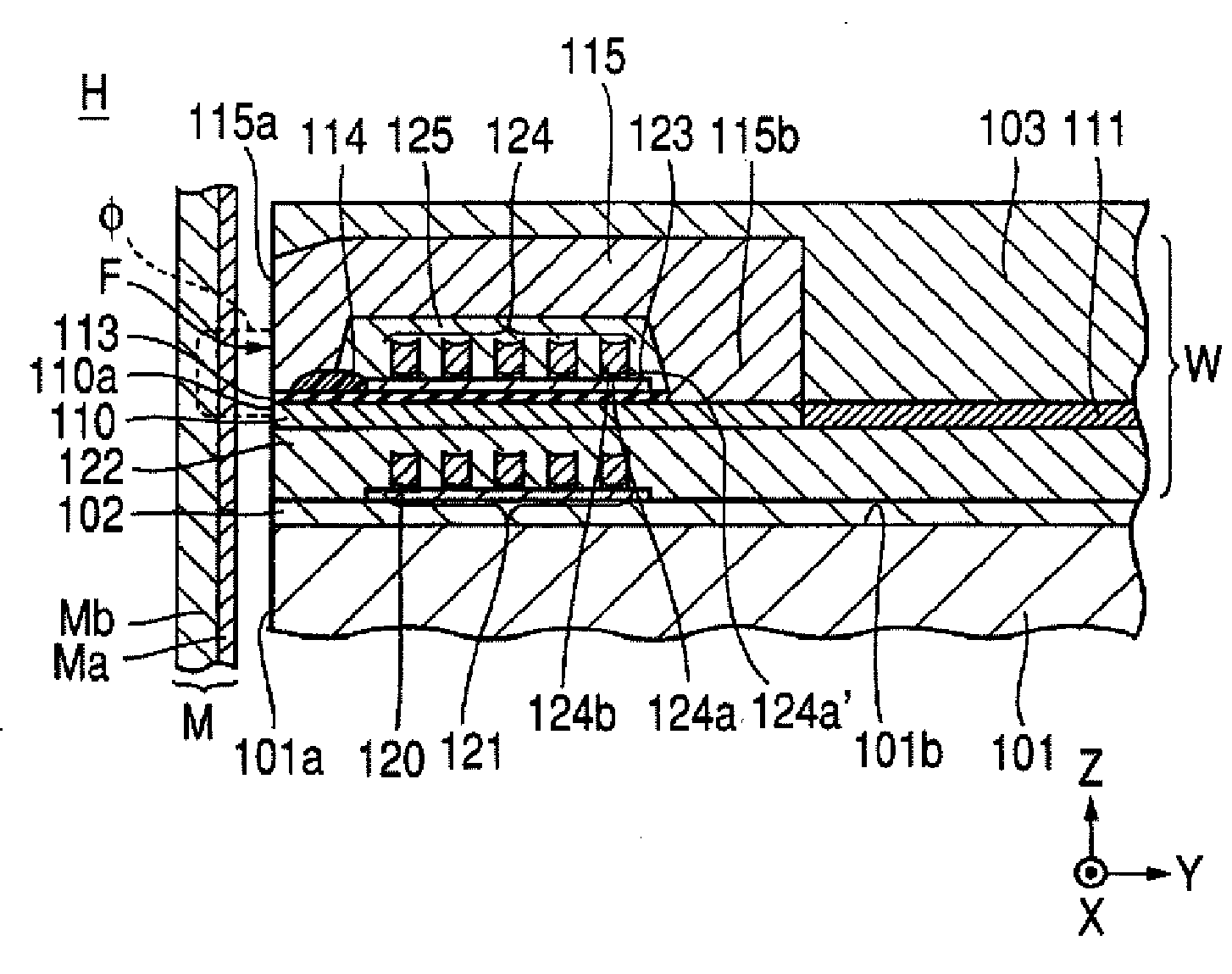
[0025]FIG. 1 is a partial longitudinal view that illustrates a laminated structure of a thin film magnetic head according to one embodiment. In FIG. 1, an X direction is defined as a track width direction, a Y direction is defined as a height direction, and a Z direction is defined as a lamination direction of respective layers that forms a thin film magnetic head.

[0026] The thin film magnetic head H is a perpendicular magnetic head that performs a recording operation by applying a perpendicular magnetic field φ to a recording medium M, and magnetizing a hard film Ma of the recording medium M in a perpendicular direction. The recording medium M includes the hard film Ma that has a high residual magnetization and located at the side of the surface of the recording medium, and a soft film Mb that has a high magnetic permeability and located closer to an inner side of the recording medium than the hard film Ma. The recording medium M has, for example, a disc shape, and rotates around ...


PUM

PropertyMeasurementUnit
recording magnetic fieldaaaaaaaaaa
thicknessaaaaaaaaaa
widthaaaaaaaaaa

Abstract

Disclosed are a thin film magnetic head that has a recoding coil and a method of forming a recording coil can sufficiently achieve a cross-sectional area of the coil and reduce coil resistance. A recording coil of a thin film magnetic head is formed as follows. First, frames, which divide a coil forming area, are formed on the plating base film for forming a coil. Further, the plating base film exposed between the frames is etched, and etching rebounds the plating base film are re-attached to a frame side wall. Then, a nonmagnetic metal layer is formed by plating on the area divided by the frames. Accordingly, the recording coil that has a thickness at both end portions in a coil width direction that is larger than that of a central portion thereof is obtained.

Description

[0001] This application claims the benefit of Japanese Patent Application No. 2005-345729 filed Nov. 30, 2005, which is hereby incorporated by reference. BACKGROUND [0002] 1. Field [0003] The present embodiments relate to a thin film magnetic head having a recording coil and a method of forming the recording coil. [0004] 2. Related Art [0005] Generally, a recording element unit of a thin film magnetic head includes a core formed of a magnetic material. A recording coil generates a recording magnetic field in the core. A magnetic gap is formed at a front end of the core. [0006] The thin film magnetic head records magnetic information on a recording medium by a leakage magnetic field that is generated from the core with the magnetic gap interposed therebetween at a surface that faces the recording medium. In this thin film magnetic head, the recording coil is generally formed by a frame-plating method. A frame, which divides a coil forming area, is formed on a plating base film by usi...

Claims


Application Information

Patent Timeline
Patent Type & Authority Applications(United States)
IPC IPC(8): G11B5/127
CPCG11B5/17G11B5/3109G11B5/3163
Inventor KOBAYASHI, KIYOSHIMORITA, SUMIHITO
Owner TDK CORPARATION
Why Eureka
Try Eureka