Multilayer inductor component and method for manufacturing multilayer inductor component

a technology of inductance components and components, applied in the direction of inductance, chemistry apparatus and processes, other domestic objects, etc., can solve the problems of coil resistance increase, coil breakage,

Active Publication Date: 2022-05-31
MURATA MFG CO LTD
View PDF17 Cites 0 Cited by
  • Summary
  • Abstract
  • Description
  • Claims
  • Application Information

AI Technical Summary

Benefits of technology

[0007]FIGS. 11A and 11B show the multilayer inductor component disclosed in Japanese Unexamined Patent Application Publication No. 2014-45081. Regarding the inductor component 1, the resistance of a coil is reduced by increasing the surface area of a coil conductor layer 2 due to porosities that are formed in the coil conductor layer 2 (coil conductor).

Problems solved by technology

Porosities 3 formed in the vicinity of the peripheral edge of the coil conductor layer 2 reduce the strength of the coil conductor layer 2 and may become a cause of an occurrence of breakage or an increase in resistance of the coil.
That is, if the resistance of the coil is reduced by using the porosities 3 in the coil conductor layer 2, as disclosed in Japanese Unexamined Patent Application Publication No. 2014-45081, various problems may occur.

Method used


Image

  • Multilayer inductor component and method for manufacturing multilayer inductor component
  • Multilayer inductor component and method for manufacturing multilayer inductor component
  • Multilayer inductor component and method for manufacturing multilayer inductor component

Examples


Embodiment Construction

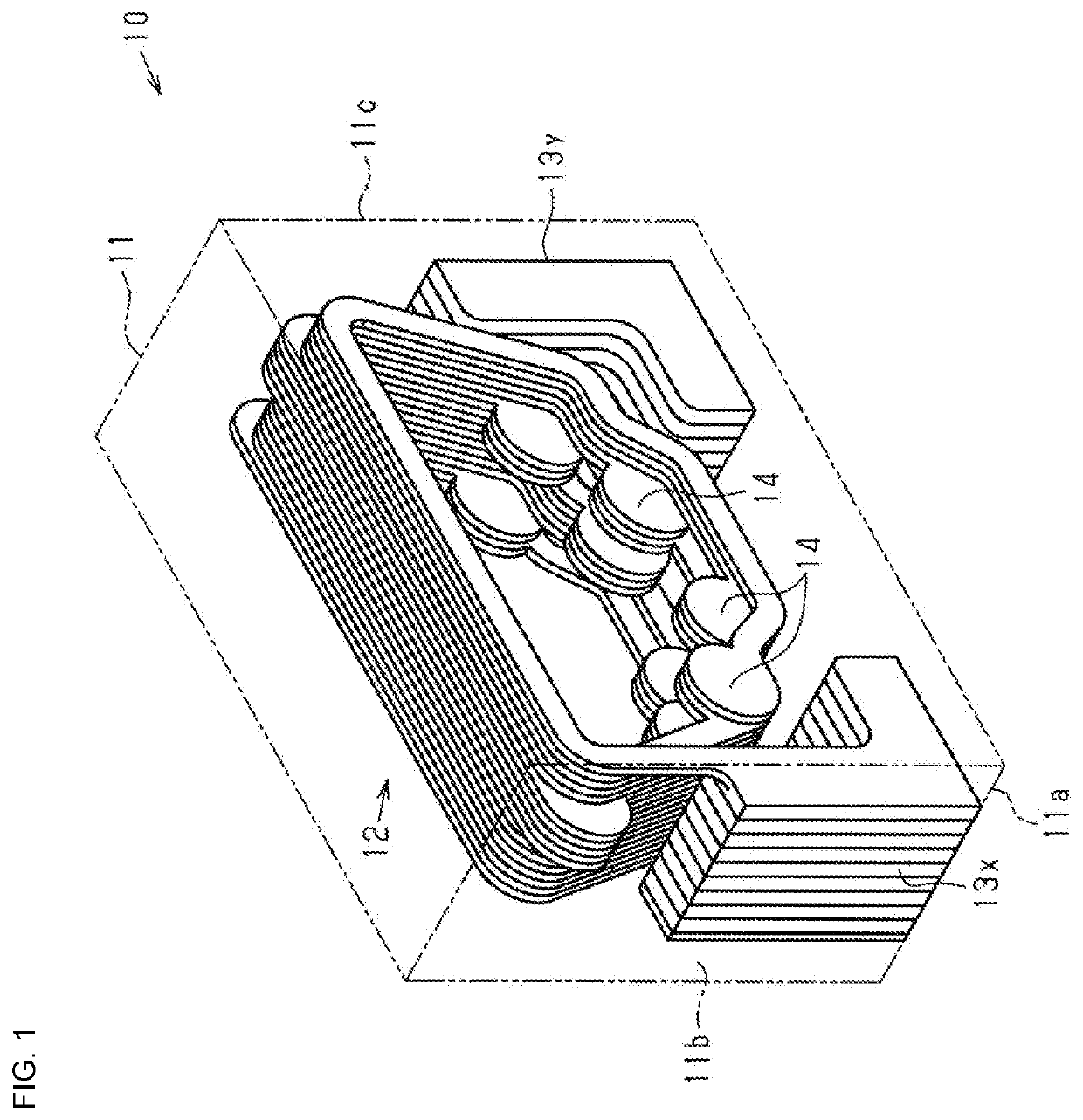
[0044]The embodiment according to an aspect of the present disclosure will be described below with reference to the drawings. A multilayer inductor component 10 shown in FIG. 1 includes an element body 11 that is an insulator, a coil 12 disposed in the element body 11, and a first outer electrode 13x and a second outer electrode 13y that are disposed along the outer surfaces of the element body 11 and that are electrically connected to a first end and a second end, respectively, of the coil 12.

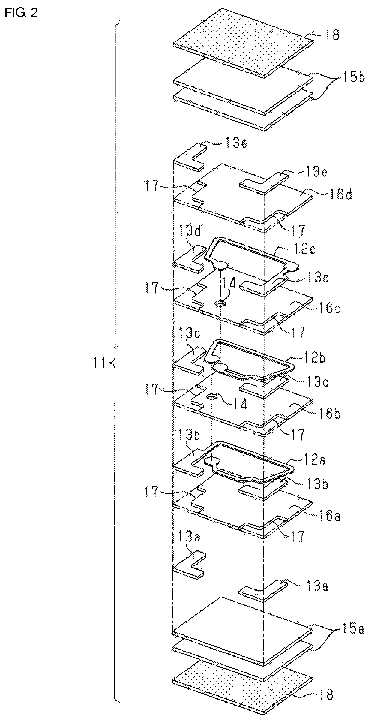
[0045]The element body 11 is formed by stacking a plurality of insulating layers, and the coil 12 is formed by electrically connecting a plurality of coil conductor layers that extend along planes corresponding to the principal surfaces of the insulating layers in the element body 11 to each other by using vias 14. The outer surfaces of the element body 11 include a mounting surface 11a on which both the first outer electrode 13x and the second outer electrode 13y are disposed, a first end sur...


PUM

PropertyMeasurementUnit
grain sizeaaaaaaaaaa

Abstract

A multilayer inductor component includes an element body that is an insulator and a coil in which a plurality of coil conductor layers that extend along planes in the element body are electrically connected to each other. Also, each of the coil conductor layers includes metal part and glass part, and the glass part include internal glass portion that is entirely included in the metal part.

Description

CROSS-REFERENCE TO RELATED APPLICATION[0001]This application claims benefit of priority to Japanese Patent Application No. 2017-240997, filed Dec. 15, 2017, the entire content of which is incorporated herein by reference.BACKGROUNDTechnical Field[0002]The present disclosure relates to a multilayer inductor component formed by stacking insulator layers and coil conductor layers, and to a method for manufacturing a multilayer inductor component.Background Art[0003]In recent years, in accordance with increases in carrier frequencies of communication devices, e.g., cellular phones, many coiled inductors compatible with high frequencies in a GHz band have been used in signal sending blocks and signal receiving blocks of these devices. A multilayer inductor component has been in actual use as one type of such an inductor. The multilayer inductor component includes an element body that is an insulator and a plurality of coil conductor layers that extend along planes in the element body, an...

Claims


Application Information

Patent Timeline
Patent Type & Authority Patents(United States)
IPC IPC(8): H01F27/28B32B15/04H01F17/00H01F27/29H01F41/04B32B15/20
CPCH01F27/2804B32B15/04B32B15/20H01F17/0013H01F27/29H01F41/043B32B2457/00H01F2017/004H01F2027/2809H01F17/02H01F27/292H01F27/323H01F2017/002H01F2017/0073
Inventor KIDO, TOMOHIROKUBOTA, MASAHIROSAKATA, TOMONORIKONDO, KENTATANABE, SHIMPEIOOTA, YOSHIYUKI
Owner MURATA MFG CO LTD
Why Eureka
Try Eureka