Magnetic field stimulation

a magnetic field and stimulation technology, applied in magnetotherapy, magnetotherapy using coils/electromagnets, magnetotherapy, etc., can solve the problems of patients declining participation, rtms treatment can be unpleasant, and agents can be limited in efficacy and other problems, to achieve the effect of less bulk, less bulk, and less hea

Active Publication Date: 2017-08-22
THE MCLEAN HOSPITAL CORP
View PDF3 Cites 1 Cited by
  • Summary
  • Abstract
  • Description
  • Claims
  • Application Information

AI Technical Summary

Benefits of technology

[0015]Various embodiments of the present invention feature systems for the induction of electric fields in air. These systems are smaller in size and less bulky compared to previously known coils and may generate less heat. In some embodiments, this is achieved, in part, by employing a coil that has at least one element having two layers, so as to decrease the overall resistance of the coil, which in turn can decrease the heat generated by the coil when compared with conventional coils. Additionally or in the alternative, in some embodiments, the coil includes only one or two elements that are cylindrical, spherical, flat, or bent in shape. Such a coil can induce the electric field outside the region enclosed by the coil, such that the patient's head need not be surrounded by the coil, which can increase patient comfort and simultaneously allows the coil size to be smaller than a coil that surrounds the patient's head. Various embodiments also feature a method of treatment by generating a varying aggregate magnetic field using a coil having one or more elements. The varying magnetic field induces an electric field in air, and a patient's brain is disposed within the region in which the field is induced for the treatment of disorders and / or the enhancement of brain function.
[0016]The delivery of these induced electric fields fall into the class of low-field magnetic stimulation (LFMS) techniques. Various embodiments of coils according to the present invention avoid one or more of the problems associated with the MRI coils described above. The invention does not utilize a constant magnetic field, and so there is no magnet such as is found in MRI systems and no size limitations imposed by the magnet, nor requirements for torque free design since there is no magnetic field to provide the torque. Second, the invention requires only one gradient field, and so two gradient coils sets and any resistive shim coils can be eliminated.
[0017]The coil module includes a coil and an optional housing for the coil. The coil includes one or more elements, each of which generates a magnetic field that induces a target electric field in air, and a subject's brain can be disposed in the region where the electric field is induced. A coil may have one or more elements that are disposed on a single surface in a non-overlapping manner. Any element may have one, two or more layers to provide reduction of resistive heating as compared to use of a single element. In one embodiment, the coil has a single element that is arranged on a circular or elliptic cylindrical surface having a first radial direction, a second radial direction, and a longitudinal direction. The dimensions of the coil along the first and second radial directions may have the same value. Such an embodiment facilitates relatively easy and / or cheap manufacturing of the coil.
[0018]In some embodiments, the coil induces an electric field in a region that is proximate to the volume enclosed by the coil. This can be achieved using a half coil design, i.e., using a coil that has two elements. This allows the coil size to be smaller than that of an MRI coil. In the region proximate to the volume enclosed by the coil, the induced electric field is not sufficiently homogeneous for imaging in an MRI system (e.g., uniformity within 5%-10%), but the homogeneity is adequate for treatment purposes. The coil elements in such a coil can have a surface that is cylindrical, spherical, rectangular, flat, or bent in shape. In various embodiments the coil does not need liquid cooling. In some embodiments, a coil element includes two or more layers of conductors, further decreasing the heat generated by the coil.
[0024]In another aspect, various embodiments of the present invention feature a system that can improve patient comfort. The system includes a pulse generator and a magnetic coil. The magnetic coil has a first element and an inner surface of the first element forms at least a part of a spherical surface. The first element is in electrical communication with the pulse generator. A parameter of the magnetic coil may be selected such that the coil produces a gradient magnetic field proximate to a region at least partially enclosed by the spherical surface. The parameter is selected such that the gradient magnetic field can induce an electric field in air up to about 50 V / m. The coil parameter may be one of a radius of the spherical surface, a polar angle of a coil segment, and an azimuth angle of the coil segment.

Problems solved by technology

These agents can be of limited efficacy and may have objectionable side effects.
Furthermore, rTMS treatment can be unpleasant, with some patients declining participation due to scalp pain induced by the apparatus (George M S, Nahas Z, Molloy M, Speer A M, Oliver N C, Li X B, Arana G W, Risch S C, Ballenger J C: A controlled trial of daily left prefrontal cortex TMS for treating depression.
One significant limitation on the use of an MRI gradient coil is its physical size, as imposed by the system, by power concerns, and by the patient.
First, the larger the gradient coil, the larger its inductance, and the more the required power to operate the coil.
A big coil usually requires more expensive amplifiers, and may impose power switching requirements that cannot be addressed merely by coil design.
The cost and the difficulty in engineering required to make magnet both increase with the increase of the inner diameter of an MRI magnet.
In MRI systems, there is a need to cool the resistive heating that is generated inside the coil during operation—most systems need to have water or liquid cooling, because the coil is tightly packed between the inner and outer size limitations.
Second, there is magnetic force on the wires in the coil when they have current in them; this causes a net force, usually in the form of a torque that can cause the coil to move.
In MRI systems, the dynamic magnetic fields are reflected from the surrounding magnet and would interfere with the desired target magnetic gradient fields.
Moreover, typical small-diameter coils do not have a strong mechanical mounting as that of the body coil, and hence, have a greater risk of movement from torque.
This poses risk of severe patient injury.
Finally, even though the MRI coils that have a relatively small diameter require less power, they still require cooling systems.
Such MRI coils, however, had significant torque and they were not safe for patient use.
Also, the reduced gradient field homogeneity was not adequate for imaging purposes.

Method used


Image

  • Magnetic field stimulation
  • Magnetic field stimulation
  • Magnetic field stimulation

Examples


Embodiment Construction

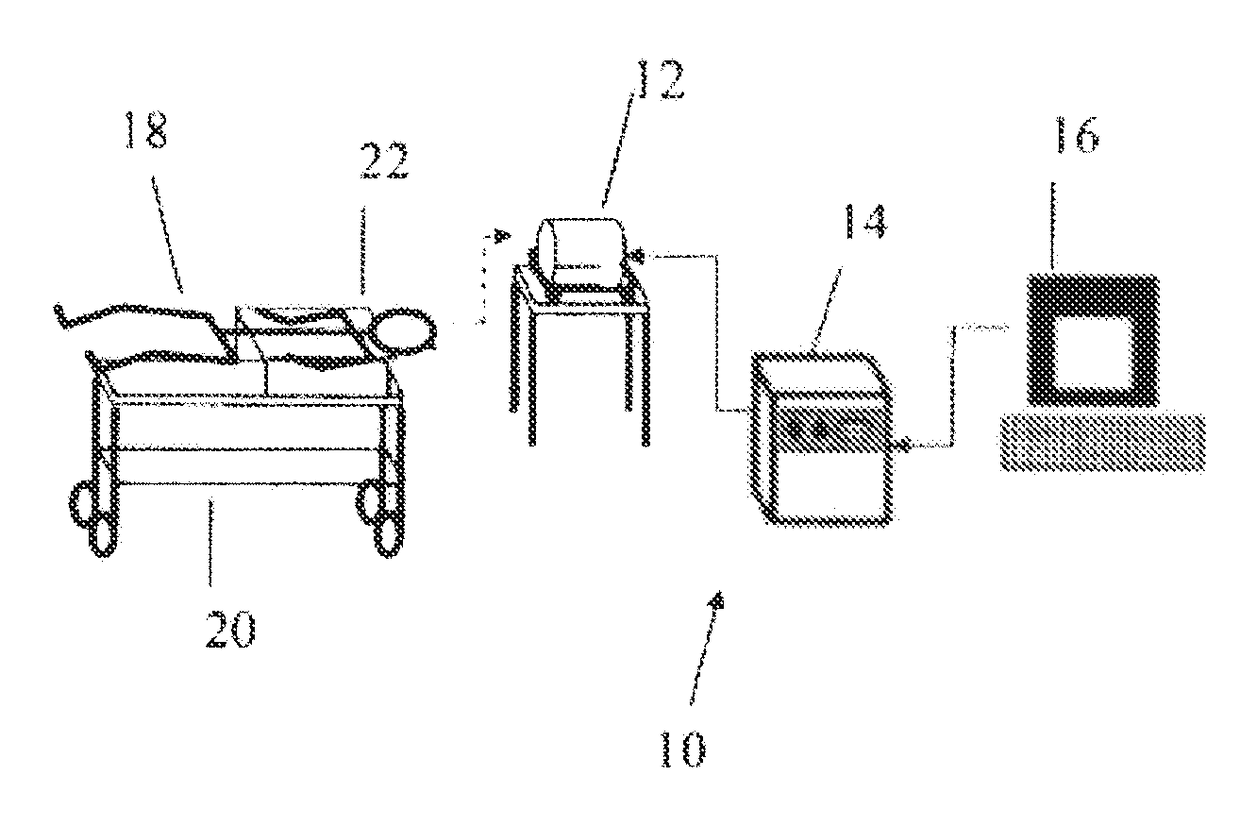
[0045]A device 10 according to an embodiment of the present invention is shown in FIG. 1. The device 10 has a magnetic coil module 12, an amplifier 14, and a waveform generator 16. The waveform generator 16 (e.g., a general-purpose programmable computer or a purpose-built electric circuit) provides an electrical pulse sequence to the amplifier 14, which amplifies the electrical signals and provides them to the magnetic coil 12. The coil 12 produces a magnetic field in response to the electrical signals received from the amplifier 14. If the electrical signals vary in time, the magnetic field typically induces an electric field in air.

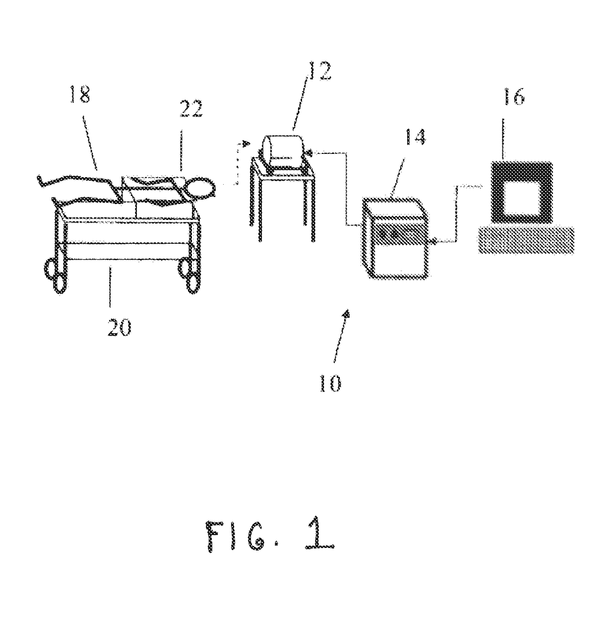
[0046]The coil module in various embodiments of an LFMS device according to the present invention includes a coil and a housing for the coil. The coil includes one or more elements, each of which generates a magnetic field that may induce a target electric field in air, and a subject's brain can be disposed in the region where the electric field is indu...


PUM


Abstract

A magnetic coil system featuring a multi-layer structure (312a, 312b), a spherical shape, or both allows for efficient generation of a gradient magnetic field that induces an electric field in air in a region proximate to the coil. By subjecting at least a portion of a person's brain to the induced electric field various psychiatric disorders can be treated.

Description

CROSS REFERENCE TO RELATED APPLICATIONS[0001]This application is the national stage of International (PCT) Patent Application No. PCT / US2012 / 057551, filed on Sep. 27, 2012, and published under PCT Article 21(2) in English, which claims priority to and benefit of U.S. Provisional Patent Application No. 61 / 539,877 titled “Low Field Magnetic Stimulation,” filed on Sep. 27, 2011, and U.S. Provisional Patent Application No. 61 / 539,893 also titled “Low Field magnetic Stimulation” and filed on Sep. 27, 2011, each of which is incorporated herein by reference in its entirety.BACKGROUND OF THE INVENTION[0002]The present invention relates generally to a system and method of induced electric fields and, more particularly, to a system that provides induced electric fields that interact with the brain.[0003]Psychiatric conditions are predominantly treated with pharmaceutical agents. For example existing treatment approaches for depression in bipolar disorder and in major depressive disorder utili...

Claims


Application Information

Patent Timeline
Patent Type & Authority Patents(United States)
IPC IPC(8): A61N2/02A61N1/40A61N2/00
CPCA61N2/02A61N1/40A61N2/006
Inventor ROHAN, MICHAEL
Owner THE MCLEAN HOSPITAL CORP
Why Eureka
Try Eureka