Expansion tank with improved single diaphragm

Inactive Publication Date: 2019-03-21
FLEXCON INDS
View PDF8 Cites 5 Cited by
  • Summary
  • Abstract
  • Description
  • Claims
  • Application Information

AI Technical Summary

Benefits of technology

The invention is about improving the sealing of expansion tanks used in industrial applications. The first improvement is a separate diaphragm coupling ring that can be easily joined to the tank using compatible equipment and processes. The second improvement is the use of tie-layers to join the diaphragm and tank sections together, creating a stronger and more reliable seal that is resistant to adhesive failures under the operating conditions of expansion tanks. Overall, these improvements enhance the performance and flexibility of expansion tanks.

Problems solved by technology

Known processes to attach diaphragms to tanks only produce adhesion between the diaphragm and the surface layers of the tank wall; these joints are highly susceptible to adhesive failures under the operating conditions of expansion tanks.

Method used


Image

  • Expansion tank with improved single diaphragm
  • Expansion tank with improved single diaphragm
  • Expansion tank with improved single diaphragm

Examples


Embodiment Construction

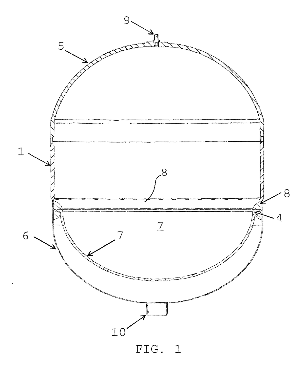
[0015]FIG. 1 is a cross section of an embodiment of a tank in accordance with this invention, with a single diaphragm, connected to a tank inner wall by a circumferential coupling ring 8; the tank is charged with pressurized gas, such as air, but empty of liquid, e.g., water. The tank comprises a substantially cylindrical housing section 1, joined to substantially hemispherical domes 5 and 6, with a single diaphragm 7 that is connected to an inside wall surface of the lower dome 6, adjacent the joint with the central cylindrical section 1. The peripheral edge 4 of the diaphragm 7 is circumferentially connected to the diaphragm coupling ring 8. Dome 5 further comprises an air valve 9, which allows the upper volume of the tank to be charged with air or an inert gas. Dome 6 further comprises a threaded connection 10, through which water can flow into the lower volume of the tank, under the diaphragm 7.

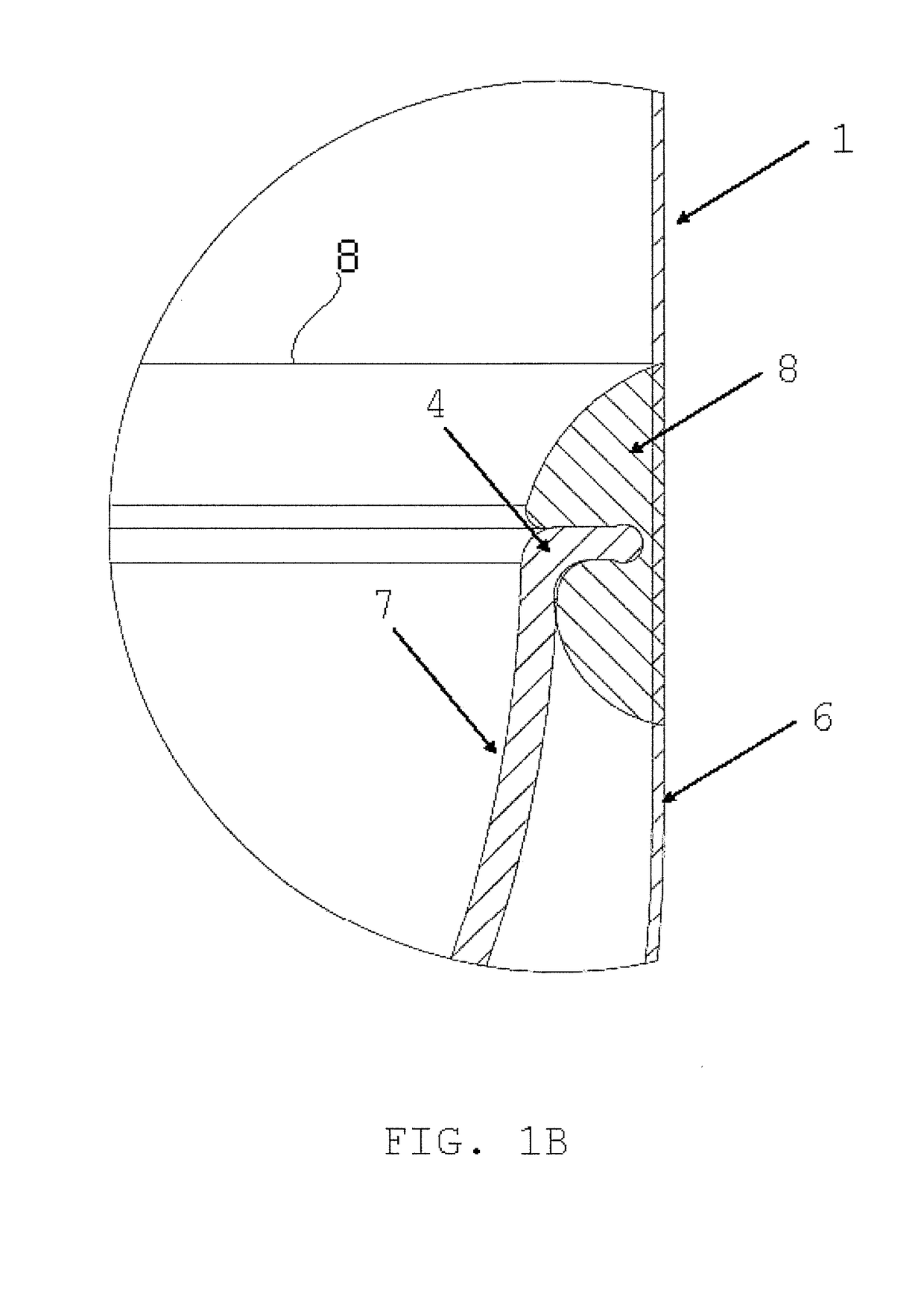
[0016]FIG. 1B shows a partial expanded view of a tank wall near the coupling ring 8. ...


PUM


Abstract

An improved expansion tank is provided for at least temporarily storing a pumped liquid under pressure, the expansion tank comprising a thin walled outer shell formed of two substantially hemispherical domes joined together, either directly or at the two ends of a central, substantially cylindrical section, and a flexible diaphragm located internally of the tank and secured to the inner surface of the shell of the tank to divide the internal volume of the tank into a fluid-tight section holding a gas under pressure and a fluid-tight section for holding an aqueous liquid under pressure. The improvement comprising diaphragm coupling ring formed as a discrete part of the diaphragm tank that can be fabricated independent of the domes and any cylinder. The diaphragm coupling ring provides a robust, leak-proof seal with the diaphragm, so that it can be connected onto an inner surface of an expansion tank in a separate, secondary operation.

Description

BACKGROUND OF THE INVENTION[0001]Expansion tanks are known for use in flow systems for controlling flow of liquid under varying pressures. Most commonly, expansion tanks comprise a substantially cylindrical housing terminated on each end by a substantially hemispherical dome section. The entire combined tank being most preferably suitable for isotensoidal reinforcement by wrapping with equally stressed filaments. In some cases, the cylindrical housing may be shortened or absent, such that the entire shape is spherical, comprised of the two domes. The housing and domes further contain a bladder-type diaphragm that divides areas of a liquid and a pressurized gas. For a general discussion of expansion tanks and bladder-type diaphragms, see U.S. Pat. No. 4,784,181 to Hilverdink entitled “Expansion Tank with a Bladder-Type Diaphragm”.[0002]In expansion tanks, it is critical to maintain a liquid and gas-tight barrier between the liquid and pressurized gas, as well as the outside environme...

Claims


Application Information

Patent Timeline
IPC IPC(8): E03B11/06F24D3/10
CPCE03B11/06F24D3/1016E03B2011/005
Inventor WIDEMAN, THOMAS W.MURPHY, LUCASBERGMILLER, TRAVISLOMBARI, ROBERTSHARFMAN, GRETCHENSHARFMAN, NELSONKENNEDY, MICHAEL
Owner FLEXCON INDS
Why Eureka
Try Eureka