Rf/dc decoupling system for RF switches based on phase change material

Active Publication Date: 2019-03-21
COMMISSARIAT A LENERGIE ATOMIQUE ET AUX ENERGIES ALTERNATIVES
View PDF11 Cites 25 Cited by
  • Summary
  • Abstract
  • Description
  • Claims
  • Application Information

AI Technical Summary

Benefits of technology

[0042]This can promote performing an independent contro

Problems solved by technology

But such a solution applied to PCM switches would require to significantly increase the control voltage necessary to switch the region of PCM material.
Such a decoupling circuit

Method used


Image

  • Rf/dc decoupling system for RF switches based on phase change material
  • Rf/dc decoupling system for RF switches based on phase change material
  • Rf/dc decoupling system for RF switches based on phase change material

Examples


Embodiment Construction

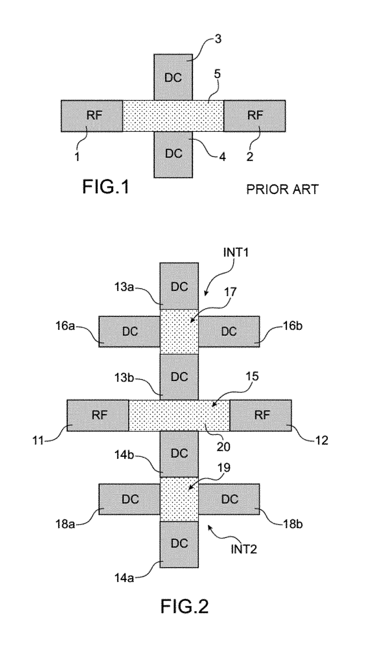
[0062]The device of FIG. 2 is first referred to, which schematically illustrates an embodiment of a switch with a phase change material.

[0063]This switch enables a connection between at least one first conductive element 11 and at least one second conductive element 12 to be modified. In this example, the conductive elements 11, 12 are elements of a circuit for conveying radio-frequency (RF) signals.

[0064]The switch is thus an RF switch able to set up or stop a connection between a first circuit portion and a second circuit portion depending on the state of at least one phase change material (PCM) arranged between both portions. The switch makes it possible to alternately convey an RF signal and prevent conveyance of an RF signal between the conductive elements 11, 12.

[0065]The first conductive element 11 and the second conductive element 12 form in this example of embodiment two terminations of an RF electrical signal transmission line, both terminations being separated from each o...


PUM


Abstract

An RF switch provided with a first region based on a phase change material disposed between a first conductive element and a second conductive element and state control means for said first region, the switch being further provided with at least one first decoupling switch provided with a second region of phase change material.

Description

TECHNICAL FIELD AND PRIOR ART[0001]The present application relates to the field of RF switches integrating a phase change material and more particularly is concerned with those made of thin films and which can be part of an integrated circuit or an electronic device.[0002]An RF switch is a structure for modifying reversibly the electrical connections between elements of an RF circuit.[0003]RF switches are usually made from electronic components such as field effect transistors or PIN (“Positive Intrinsic Negative”) diodes or using MEMS type electro-mechanical relays.[0004]RF switches integrating a phase change material (PCM) have also appeared.[0005]The operation of an RF switch based on a PCM material is typically based on two states that this material is likely to assume:[0006]a high-resistivity amorphous state, which corresponds to an “OFF” state of the switch during which the transmission of an RF signal between at least two terminals is prevented,[0007]a low-resistivity crystal...

Claims


Application Information

Patent Timeline
IPC IPC(8): H01L27/24H01L45/00
CPCH01L27/2463H01L45/1226H01L27/2409H01L45/126H01L45/144H10N70/801H10N70/231H01P1/10H10N70/253H10N70/823H10N70/8613H10N70/8828H10B63/80H10B63/20H10N70/8413
Inventor REIG, BRUNOLEON, ALEXANDRESAINT-PATRICE, DAMIEN
Owner COMMISSARIAT A LENERGIE ATOMIQUE ET AUX ENERGIES ALTERNATIVES
Why Eureka
Try Eureka