Path module for a linear motor, modular linear motor system and method to control same

Inactive Publication Date: 2007-01-30
ROCKWELL AUTOMATION
View PDF29 Cites 25 Cited by
  • Summary
  • Abstract
  • Description
  • Claims
  • Application Information

AI Technical Summary

Benefits of technology

[0016]In accordance with one aspect, a plurality of the modules are connected together to define a path having a desired shape and length. The controller of each module receives control information from a system controller via a communications link. The system controller receives position information indicative of the position of each of one or more stages moveable along the path. The system controller determines the absolute position of each stage relative to the path and provides instru

Problems solved by technology

The maximum force obtainable from a linear motor is limited by the allowable temperature rise in the armature windings.
The need for a cable loop connecting moving and stationary elements is inconvenient, and limits the flexibility with which a system can be designed.
In addition, the wiring harness adds additional weight to the moving element of the linear motor.
Furthermore, manufacturing of a linear motor employing a wiring harness incurs additional cost of material and assembly labor.
The cost of producing a linear motor is increased when each assembly is custom designed to a users needs, with new tooling required for each such design.
The stocking of co

Method used


Image

  • Path module for a linear motor, modular linear motor system and method to control same
  • Path module for a linear motor, modular linear motor system and method to control same
  • Path module for a linear motor, modular linear motor system and method to control same

Examples


Example

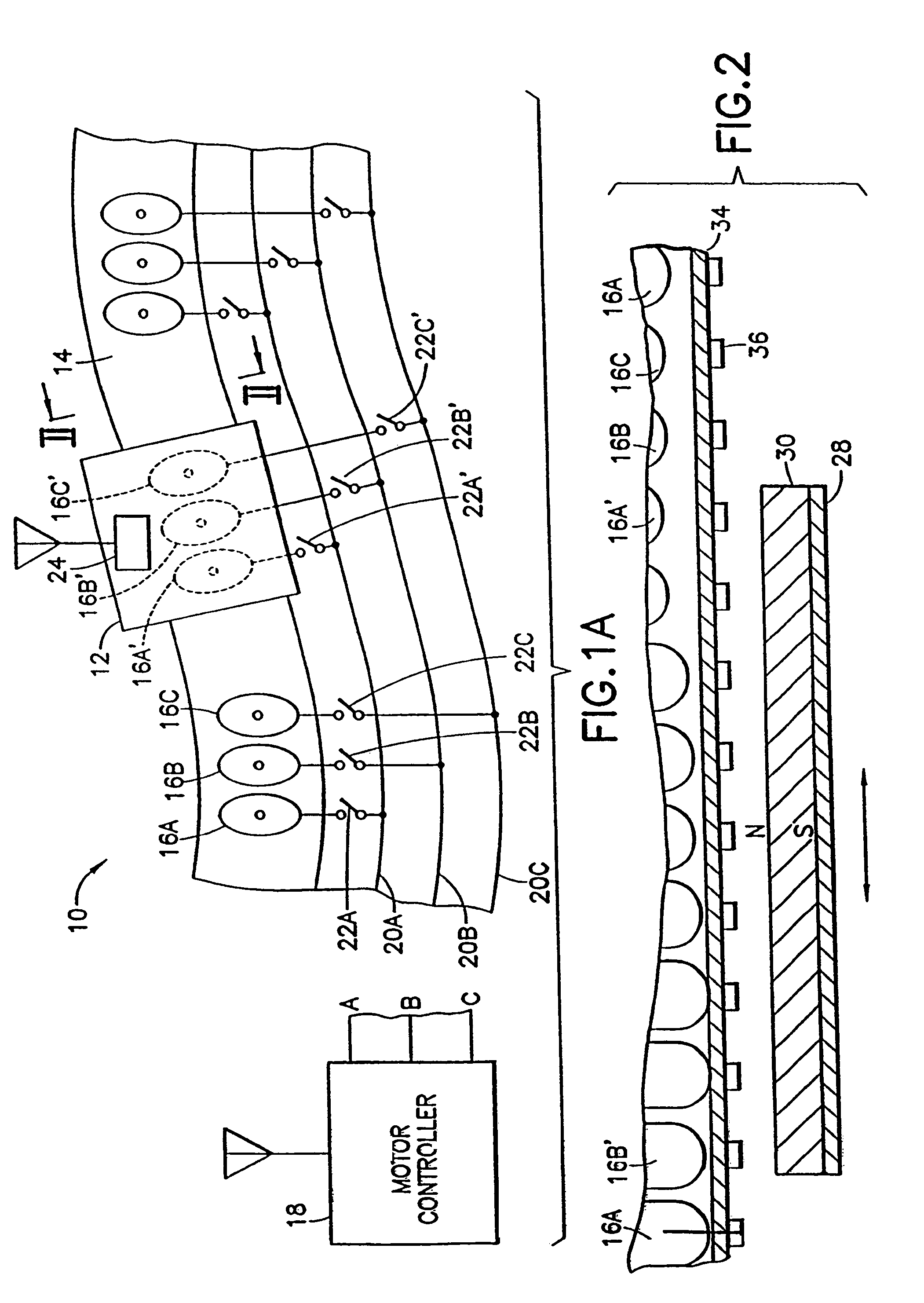
[0055]Referring to FIG. 1A, there is shown, generally at 10, a linear motor according to an aspect of the invention. A movable stage 12 is supported and guided in any convenient manner along a path 14. Path 14 includes therein repeating sets of three armature windings 16A, 16B and 16C for receiving, respectively, phases A, B and C of three-phase drive power produced by a motor controller 18. Phase A of the drive power from motor controller 18 is connected on a phase-A conductor 20A to terminals of normally-open phase-A switches 22A. Each phase-A switch is connected to its associated phase-A armature winding 16A. Similarly, phase-B and phase-C drive power are connected on phase-B and phase-C conductors 20B and 20C to terminals of phase-B and phase-C switches 22B and 22C, respectively. Armature windings 16A, 16B and 16C of each set may be noninterleaved. That is, they lie side by side, not overlapping as is the case in some prior art linear motors.

[0056]Switches 22A, 22B and 22C remai...


PUM


Abstract

A path module for a linear motor system includes a controller coupled to one or more amplifiers that are operative to control associated windings in the module. The controller receives control information via a communications link. The controller controls the amplifier based on the received control information so as to selectively energize the associated windings in the module. In one aspect, a plurality of such modules may be connected together to form a path along which one or more stages are moveable according to energization of the windings in the path.

Description

RELATED APPLICATIONS[0001]The present application is a continuation of U.S. patent application Ser. No. 10 / 909,439, filed Aug. 2, 2004 now U.S. Pat. No. 6,975,081, entitled “PATH MODULE FOR A LINEAR MOTOR, MODULAR LINEAR MOTOR SYSTEM AND METHOD TO CONTROL SAME”, which is a continuation of U.S. patent application Ser. No. 09 / 884,410, filed Jun. 19, 2001 now U.S. Pat. No. 6,803,681, entitled “PATH MODULE FOR A LINEAR MOTOR, MODULAR LINEAR MOTOR SYSTEM AND METHOD TO CONTROL SAME”, which is a continuation-in-part of U.S. patent application Ser. No. 09 / 415,166 filed Oct. 8, 1999 now U.S. Pat. No. 6,274,952 entitled “CLOSED-PATH LINEAR MOTOR”, which is a continuation of U.S. patent application Ser. No. 09 / 069,324 entitled “CLOSED-PATH LINEAR MOTOR” filed Apr. 29, 1998, now U.S. Pat. No. 5,994,798, which is a continuation-in-part of U.S. patent application Ser. No. 09 / 031,009 entitled “LINEAR MOTOR HAVING AUTOMATIC ARMATURE WINDING SWITCHING AT MINIMUM CURRENT POINTS” filed Feb. 26, 1998, ...

Claims


Application Information

Patent Timeline
IPC IPC(8): H02P1/00
CPCH02P25/06
Inventor FAIZULLABHOY, MUSTANSIRCHITAYAT, ANWARCARDAMONE, JOSEPH
Owner ROCKWELL AUTOMATION
Why Eureka
Try Eureka