

Wheel assembly and robot cleaner having same
- Summary
- Abstract
- Description
- Claims
- Application Information
AI Technical Summary
Benefits of technology
Problems solved by technology
Method used
Image

Examples
first embodiment
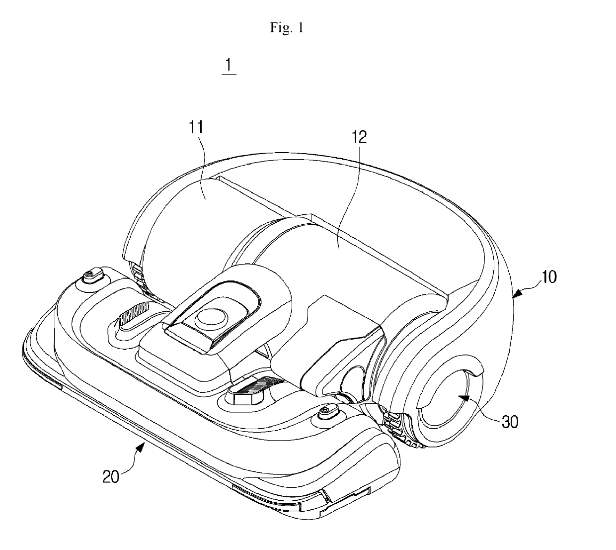
[0042]FIG. 1 is a view illustrating a robot cleaner 1 according to the present disclosure.
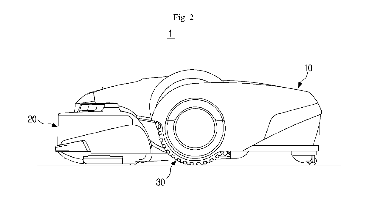
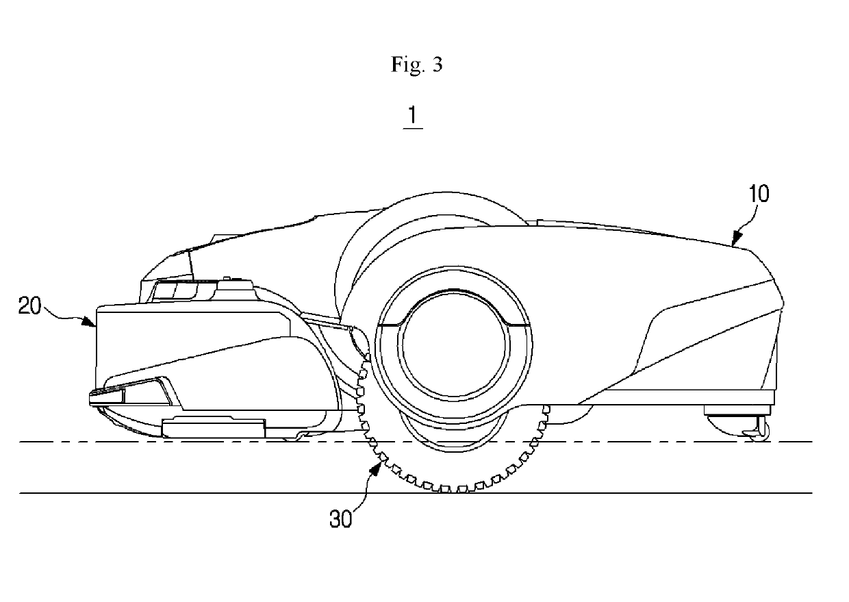
[0043]The robot cleaner 1 includes a main body 10 forming an exterior thereof, a suction unit 20 coupled to one side of the main body 10 and configured to suction air around a floor, and wheel assemblies 30 disposed at both sides of the main body 10 as illustrated inFIG. 4 and configured to allow the main body 10 to move on a ground surface.
[0044]Referring back to FIG. 1, the main body 10 includes a fan motor 11 configured to generate a suction force and a dust collecting container 12 configured to store foreign materials such as dust filtered from air suctioned through the suction unit 20.
[0045]The suction unit 20 suctions foreign materials of a ground surface with air using a suction force transmitted from the fan motor 11. Although not illustrated in the drawings, a brush is rotatably installed in the suction unit 20 to swipe dust on the ground surface upward.
[0046]In a case in which the rob...
second embodiment
[0065]Hereinafter, a wheel assembly according to the present disclosure will be described in detail with reference to the accompanying drawings.
[0066]As illustrated in FIGS. 12 and 13, a wheel assembly 30 according to the second embodiment of the present disclosure includes a drive wheel 32, a rotation arm 31, an elastic member 34, and a wheel housing 35 which have the same forms as those of the previous embodiment.
[0067]In addition, a second end of the elastic member 34 is moveably supported by a guide portion 313a through a roller 371 moveably installed at the guide portion 313a, a bearing 372 installed at a center of the roller 371, and a holder 374 formed in a U shape and having both ends coupled to a bearing 372 via a shaft 373. The second hook 34c of the elastic member 34 is supported by being hooked at a center of the holder 374. Due to the above configuration, the second end of the elastic member 34 may be more easily moved along the guide portion 313a.
[0068]The guide porti...
third embodiment
[0069]Hereinafter, a wheel assembly 30 according to the present disclosure will be described in detail with reference to the accompanying drawings.
[0070]As illustrated in FIGS. 17 and 18, the wheel assembly according to the third embodiment of the present disclosure includes a drive wheel 32, a rotation arm 31, an elastic member 34, and a wheel housing which have the same forms as those of the previous embodiment, and a guide 313-4 includes a guide portion 313a-4 formed in a rack gear form.
[0071]In addition, a second end of the elastic member 34 is moveably installed at a guide portion 313a through a pinion 381 tooth-engaged with the guide portion 313a-4 formed in the rack gear form and a holder 383 formed in a U shape and having both ends rotatably coupled to the pinion 381 by a shaft 382. A second hook 34c of the elastic member 34 is supported by being hooked at a center of the holder 383. Due to the above configuration, the second end of the elastic member 34 may be more easily m...
PUM
 Abstract
Description
Claims
Application Information