
Rotation transmission mechanism and spinning reel for fishing having the same

Active Publication Date: 2019-04-11
SHIMANO INC
View PDF5 Cites 3 Cited by
  • Summary
  • Abstract
  • Description
  • Claims
  • Application Information

AI Technical Summary

Benefits of technology

The patent aims to minimize the shaking and unevenness in the movement of gears in a rotation transmission mechanism. The technical effect of the patent is to improve the stability and efficiency of the gear system.

Problems solved by technology

Thus, axial wobbling of the intermediate gear is not transmitted easily to the reciprocating mechanism.

Method used


Image

  • Rotation transmission mechanism and spinning reel for fishing having the same
  • Rotation transmission mechanism and spinning reel for fishing having the same
  • Rotation transmission mechanism and spinning reel for fishing having the same

Examples


Embodiment Construction

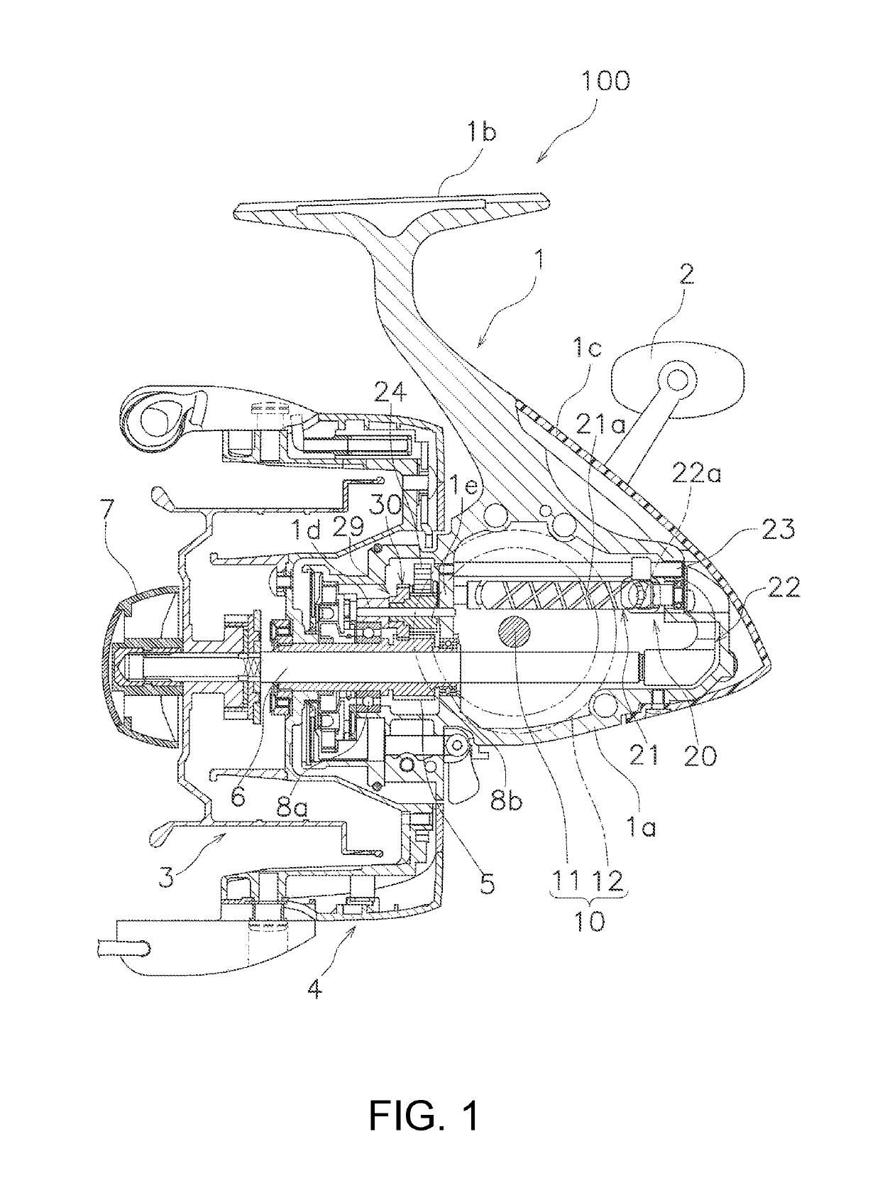
[0023]In the following descriptions, the term front-rear means that the direction in which a fishing line is pulled out at the time of fishing is referred to as the front and that the direction opposite thereto is referred to as the rear. In addition, the terms left and right refer to the left-hand side and the right-hand side of a spinning reel 100 viewed from behind. Also, the direction in which a spool shaft 6 extends is referred to as an axial direction.

[0024]The spinning reel 100 employing an embodiment of the present disclosure includes a reel body 1, a handle 2, a spool 3, a rotor 4, and a pinion gear 5.

[0025]The reel body 1 has a casing 1a having one side (the left side, in this case) opened, a rod mounting portion 1b formed integrally with the casing 1a, and a cover 1c covering the rear of the casing 1a. The opened portion of the casing 1a is covered by a lid, not shown, and a rotor drive mechanism 10 that drives the rotor 4, a reciprocating mechanism 20 that evenly winds a...


PUM


Abstract

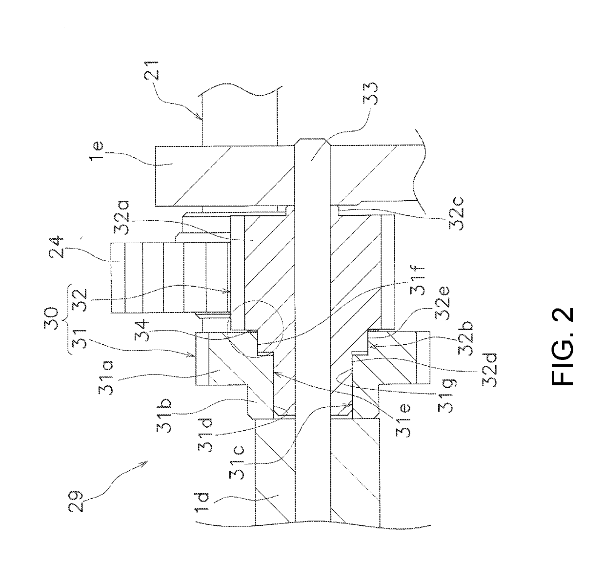
A rotation transmission mechanism of a spinning reel for fishing transmits a rotation of a handle to a driven gear of a reciprocating mechanism. The rotation transmission mechanism includes an intermediate gear, a shaft member, and a biasing member. The intermediate gear rotates in response to rotation of the handle, meshes with the driven gear, and transmits the rotation of the handle to the driven gear. The shaft member rotatably supports the intermediate gear. The biasing member biases the intermediate gear in an axial direction of the shaft member.

Description

CROSS-REFERENCE TO RELATED APPLICATIONS[0001]This application claims priority to Japanese Patent Application No. 2017-196139, filed Oct. 6, 2017. The contents of that application are herein incorporated by reference in their entirety.BACKGROUNDTechnical Field[0002]The present disclosure relates to a rotation transmission mechanism, particularly to a rotation transmission mechanism of a spinning reel for fishing that transmits a rotation of a handle to a driven gear of a reciprocating mechanism, and a spinning reel for fishing having this rotation transmission mechanism.Background Information[0003]A spinning reel for fishing has a reciprocating mechanism for evenly winding a fishing line on a spool. The reciprocating mechanism disclosed in Japanese Patent Application Laid-open No. 2015-128403 has a driven gear to which rotation of the handle is transmitted. The rotation of the handle is transmitted to the driven gear via a deceleration mechanism. The deceleration mechanism includes a...

Claims


Application Information

Patent Timeline
IPC IPC(8): A01K89/01
CPCA01K89/0114A01K89/01121
Inventor SAITO, KEITAKAMATSU, TAKUJIIKEBUKURO, SATOSHI
Owner SHIMANO INC
Learn More