Optical disc device

a technology of optical discs and optical discs, applied in the field of optical disc devices, can solve the problems of inadvertent drop of the user's mobile device, and achieve the effect of reducing the strength of the components or the entire structure of reducing the force applied to the driving force transmission mechanism

Inactive Publication Date: 2011-12-13
PANASONIC CORP
View PDF14 Cites 0 Cited by
  • Summary
  • Abstract
  • Description
  • Claims
  • Application Information

AI Technical Summary

Benefits of technology

[0038]According to the present invention, the distance between the engaging section and the rotating axis of the optical pickup is longer than the distance between the center of gravity of the entire optical pickup and the rotating axis of the optical pickup. Therefore, when the entire apparatus receives an impact force in the rotating direction of the optical pickup, the force applied on the center of gravity of the optical pickup is divided into a component applied on the shaft for supporting the optical pickup and a component applied on the driving force transmission mechanism. As a result, the force applied on the driving force transmission mechanism is decreased. Therefore, the driving force transmission mechanism only needs to provide a small stopping force to prevent the optical pickup from rotating due to the impact force. The strength of the components or the entire structure of the driving force transmission mechanism can also be reduced.
[0039]Since the driving force transmission mechanism includes a worm, inverse transmission of the driving force toward the driving source can be avoided by a simple structure when the optical pickup receives an impact force in a rotation direction thereof.

Problems solved by technology

Hence, the user may inadvertently drop the mobile device.

Method used


Image

  • Optical disc device
  • Optical disc device
  • Optical disc device

Examples


embodiment 1

[0177]Hereinafter, an optical disc apparatus in Embodiment 1 according to the present invention will be described.

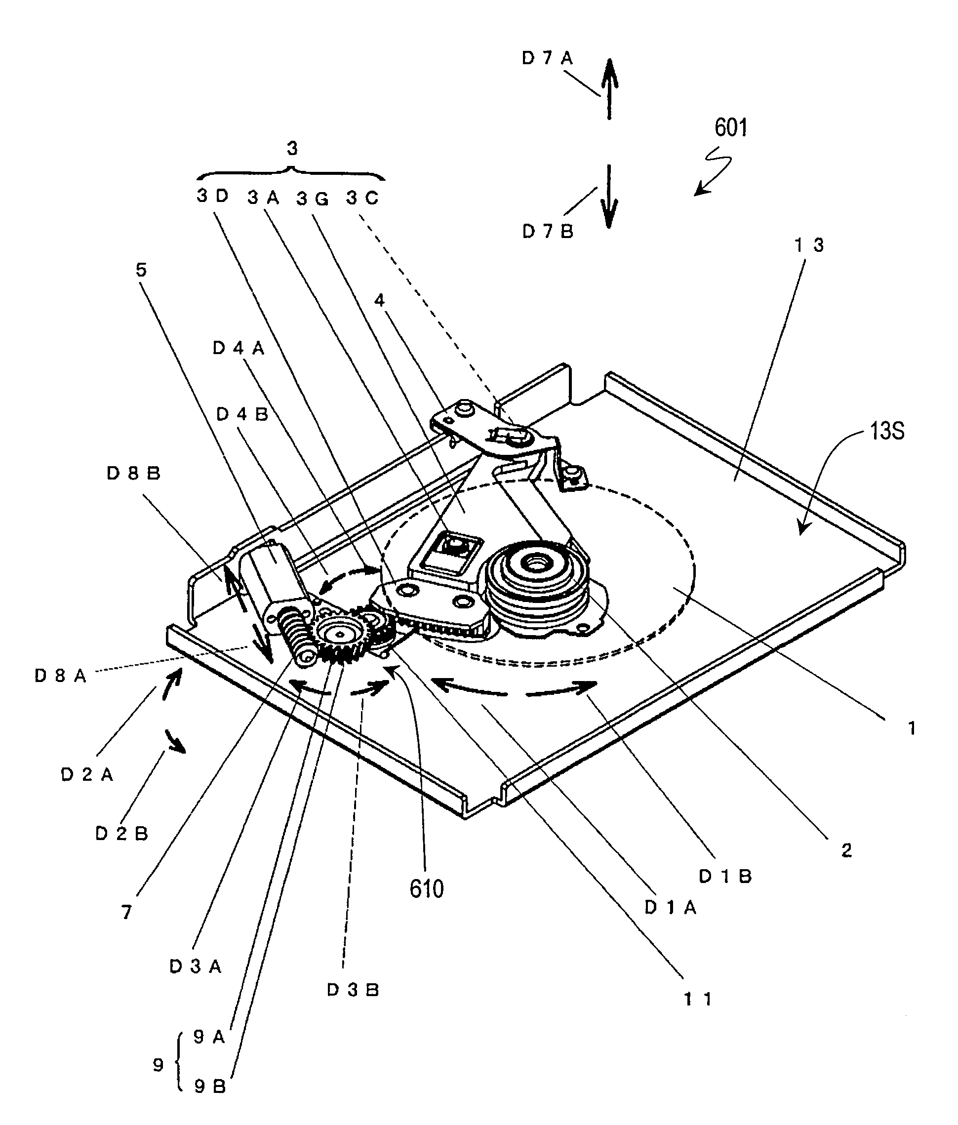
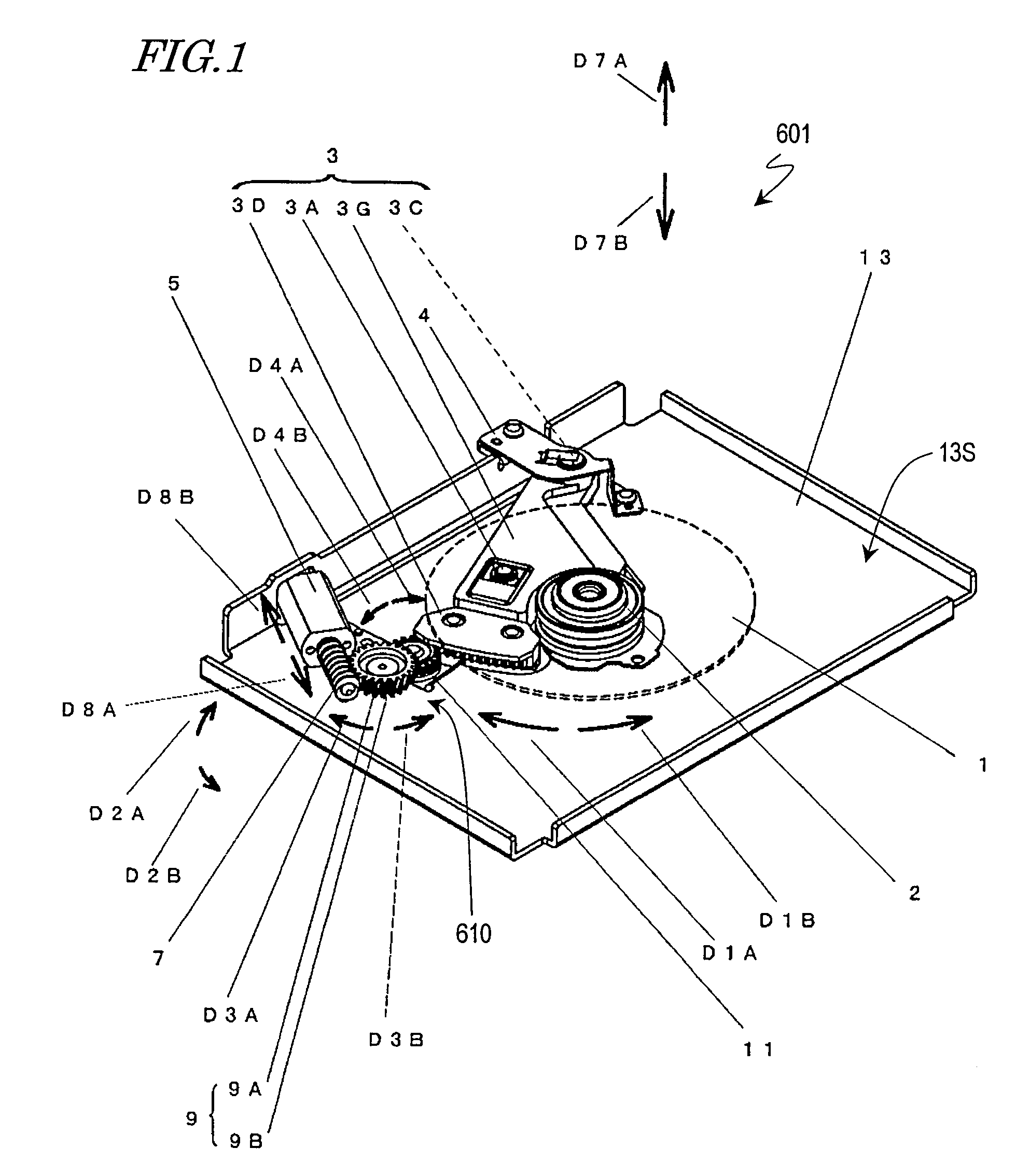
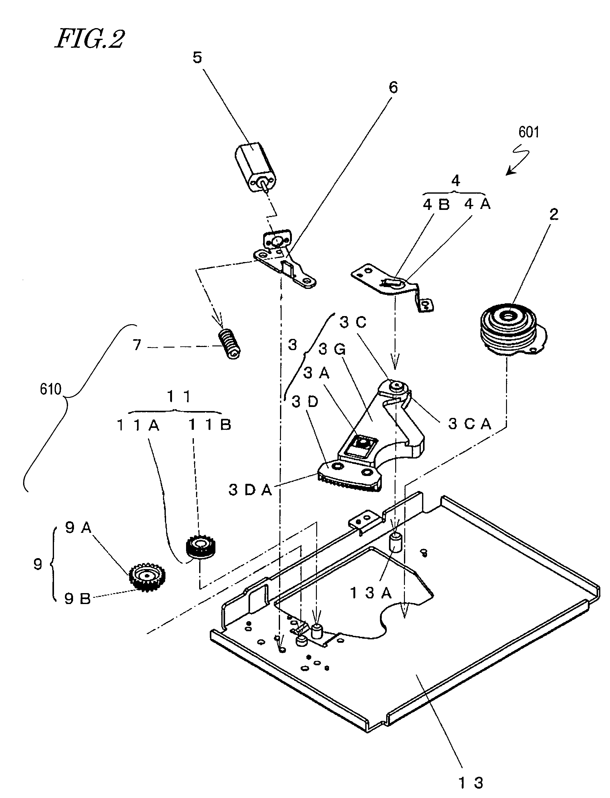
[0178]FIG. 1 is an isometric view showing an overall structure of an optical disc apparatus 601, and FIG. 2 is an exploded isometric view of the optical disc apparatus 601.

[0179]The optical disc apparatus 601 includes a disc motor 2, an optical pickup 3, a transportation motor 5, a driving force transmission mechanism 610, and a base main body 13.

[0180]The disc motor 2 is a disc rotation mechanism for allowing the optical disc 1 to be placed thereon and rotating the optical disc 1, and is supported by the base main body 13. The optical disc 1 is represented with the dashed line in FIG. 1, and a face thereof facing the optical pickup 3 is an information recording face.

[0181]The optical pickup 3 includes an objective lens 3A and irradiates the information recording face of the optical disc 1 placed on the disc motor 2 with a light beam through the objective lens 3A. By mod...

embodiment 2

[0224]Hereinafter, an optical disc apparatus in Embodiment 2 according to the present invention will be described.

[0225]FIG. 10 is an isometric view showing a structure of an optical disc apparatus 602. Unlike in Embodiment 1, the optical disc apparatus 602 includes an optical pickup 3′ including a balancing weight 3E. As shown in FIG. 10, the structures and functions of the disc motor 5, the driving force transmission mechanism 610, the pickup holding section 4 and the components of the optical pickup 3′ other than the balancing weight 3E are as described in Embodiment 1.

[0226]As shown in FIG. 11, the balancing weight 3E includes, for example, five plate-like members. As shown in FIG. 11, three upper members are fixed via a screw 33, and two lower members are fixed via a screw 33, while being positioned with respect to a weight attaching part 3GE provided on the pickup base 3G. It is preferable that the pickup gear 3D is formed of a material suitable to a gear, like in Embodiment 1...

embodiment 3

[0242]Hereinafter, an optical disc apparatus in Embodiment 3 according to the present invention will be described. FIG. 15 is an partially exploded isometric view showing a part of the elements of an optical disc apparatus 603. The optical disc apparatus 603 includes a pickup holding section 54 having a different structure from that of the corresponding element in Embodiment 1. As shown in FIG. 15, the structures and functions of the optical pickup 3, the disc motor 5, and the driving force transmission mechanism 610 are as described in Embodiment. To the pickup holding section 54, a plate-like shaft forcing spring 64 formed separately is attached via a screw or the like.

[0243]FIG. 16(a) is a plan view of the optical disc apparatus 603 shown in FIG. 15 seen in the direction of arrow D7B. S3 is a partial cross-sectional view taken along line P3-P4. FIG. 16(b) is an enlarged view of S3. As shown in FIG. 16(b), the shaft forcing spring 64 forces the support boss 3C via the projection 3...


PUM

PropertyMeasurementUnit
diameteraaaaaaaaaa
diameteraaaaaaaaaa
outer diameter Ddaaaaaaaaaa

Abstract

An optical disc apparatus according to the present invention includes a disc rotation mechanism 2 for allowing an optical disc 1 having an information recording face to be placed thereon and rotating the optical disc 1; an optical pickup 3 including an engaging section and irradiating the information recording face with a light beam to perform at least one of information recording and information reproduction; a base main body 13 for rotatably supporting the optical pickup and having the disc rotation mechanism; a driving source 5, supported by the base main body, for generating a force for rotating the optical pickup; and a driving force transmission mechanism 610 supported by the base main body, including a worm, and engaged with the engaging section to transmit a driving force of the driving source to the optical pickup, thereby rotating the optical pickup. A distance between the engaging section and a rotating axis of the optical pickup is longer than a distance between the center of gravity of the optical pickup and the rotating axis of the optical pickup.

Description

TECHNICAL FIELD[0001]The present invention relates to an optical disc apparatus including a pickup for performing at least one of recording to a disc or reproduction from a disc.BACKGROUND ART[0002]Data recording and reproduction systems for recording, for example, video, audio or computer data on a disc-like recording medium and reproducing such data from a recording medium are widely used. Specifically, optical discs such as CDs (compact discs), DVDs (digital versatile discs), BDs (Blu-ray discs) and the like, and optical disc apparatuses compatible therewith; opto-magnetic discs such as MOs (magnetic optical discs), MDs (minidiscs) and the like, and opto-magnetic disc apparatuses compatible therewith; and magnetic discs such as FDs (floppy discs) and magnetic disc apparatuses compatible therewith are already in wide use in the society.[0003]Because of the rapid increase of data amount of such information in recent years, a recording medium having a large capacity is desired. Amon...

Claims


Application Information

Patent Timeline
Patent Type & Authority Patents(United States)
IPC IPC(8): G11B7/00
CPCG11B17/0284G11B33/121G11B7/08576G11B7/0946
Inventor EZAWA, KOZOINATA, MASAHIROTAKIZAWA, TERUYUKITOMITA, HIRONORI
Owner PANASONIC CORP
Why Eureka
Try Eureka