Vehicle, driving device and control method thereof

a technology of driving device and control method, which is applied in the direction of electric devices, machines/engines, process and machine control, etc., can solve the problems of inability to rapidly output the energy used for raising the rotation speed of the internal combustion engine cannot be reduced, and the driving force required by the driver cannot be obtained. , to achieve the effect of reducing the energy used for raising the rotation speed of the internal combustion engine, reducing the energy consumption and increasing the driving for

Active Publication Date: 2012-05-15
TOYOTA JIDOSHA KK +1
View PDF15 Cites 3 Cited by
  • Summary
  • Abstract
  • Description
  • Claims
  • Application Information

AI Technical Summary

Benefits of technology

[0005]A vehicle, driving device and control method thereof of the present invention have an object to deal with a rapid change in a driving force required in the middle of gear shifting of a transmission with rapidity. The vehicle, driving device and control method thereof of the present invention have another object to reduce a torque shock which can be generated at gear shifting of the transmission.
[0008]In the vehicle of the present invention, when the gear of the transmission mechanism is not shifted, the internal combustion engine, the electric power-mechanical power input output mechanism and the motor are controlled so that running is made by the driving force based on the required driving force required for running with a change within the first change speed of the rotation speed of the internal combustion engine, and when the gear of the transmission mechanism is shifted, the gear of the transmission mechanism is shifted with a change within the second change speed smaller than the first change speed of the rotation speed of the internal combustion engine, and the internal combustion engine, the electric power-mechanical power input output mechanism, the motor, and the transmission mechanism are controlled so that running is made by the driving force based on the required driving force required for running. That is, while the gear of the transmission mechanism is shifted, the change speed of the rotation speed of the internal combustion engine is made smaller than that when the gear is not changed. By this arrangement, even if the required driving force is rapidly increased in the middle of the gear shifting of the transmission mechanism, energy used for raising the rotation speed of the internal combustion engine can be reduced and power to be outputted to the first axle can be increased, by which a larger driving force can be obtained for running. As a result, the rapid change in the driving force required in the middle of the gear shifting of the transmission mechanism can be coped with quickly. Moreover, the torque shock which can be generated at gear shifting of the transmission mechanism can be reduced. Here, the first change speed and the second change speed may be made the maximum change speed at an increase of the rotation speed of the internal combustion engine.
[0012]In one preferable embodiment of the driving device of the present invention, when the gear of the transmission mechanism is not shifted, the internal combustion engine as well as the electric power-mechanical power input output mechanism and the motor are controlled so that running is made by the driving force based on the required driving force required for running with a change within the first change speed of the rotation speed of the internal combustion engine, and when the gear of the transmission mechanism is shifted, the gear of the transmission mechanism is shifted with a change within the second change speed smaller than the first change speed of the rotation speed of the internal combustion engine, and the internal combustion engine as well as the electric power-mechanical power input output mechanism, the motor, and the transmission mechanism are controlled so that running is made by the driving force based on the required driving force required for running. That is, while the gear of the transmission mechanism is shifted, the change speed of the rotation speed of the internal combustion engine is made smaller than that when the gear is not changed. By this arrangement, even if the required driving force is rapidly increased in the middle of the gear shifting of the transmission mechanism, energy used for raising the rotation speed of the internal combustion engine can be reduced and power to be outputted to the first axle can be increased, by which a larger driving force can be obtained for running. As a result, the rapid change in the driving force required in the middle of the gear shifting of the transmission mechanism can be coped with quickly. Moreover, the torque shock which can be generated at gear shifting of the transmission mechanism can be reduced.
[0014]In one preferable embodiment of the control method of the vehicle of the present invention, when the gear of the transmission mechanism is not shifted, the internal combustion engine, the electric power-mechanical power input output mechanism and the motor are controlled so that running is made by the driving force based on the required driving force required for running with a change within the first change speed of the rotation speed of the internal combustion engine, and when the gear of the transmission mechanism is shifted, the gear of the transmission mechanism is shifted with a change within the second change speed smaller than the first change speed of the rotation speed of the internal combustion engine, and the internal combustion engine, the electric power-mechanical power input output mechanism, the motor, and the transmission mechanism are controlled so that running is made by the driving force based on the required driving force required for running. That is, while the gear of the transmission mechanism is shifted, the change speed of the rotation speed of the internal combustion engine is made smaller than that when the gear is not changed. By this arrangement, even if the required driving force is rapidly increased in the middle of the gear shifting of the transmission mechanism, energy used for raising the rotation speed of the internal combustion engine can be reduced and power to be outputted to the first axle can be increased, by which a larger driving force can be obtained for running. As a result, the rapid change in the driving force required in the middle of the gear shifting of the transmission mechanism can be coped with quickly. Moreover, the torque shock which can be generated at gear shifting of the transmission mechanism can be reduced.
[0016]In one preferable embodiment of the control method of the driving device of the present invention, when the gear of the transmission mechanism is not shifted, the internal combustion engine as well as the electric power-mechanical power input output mechanism and the motor are controlled so that running is made by the driving force based on the required driving force required for running with a change within the first change speed of the rotation speed of the internal combustion engine, and when the gear of the transmission mechanism is shifted, the gear of the transmission mechanism is shifted with a change within the second change speed smaller than the first change speed of the rotation speed of the internal combustion engine, and the internal combustion engine as well as the electric power-mechanical power input output mechanism, the motor, and the transmission mechanism are controlled so that running is made by the driving force based on the required driving force required for running. That is, while the gear of the transmission mechanism is shifted, the change speed of the rotation speed of the internal combustion engine is made smaller than that when the gear is not changed. By this arrangement, even if the required driving force is rapidly increased in the middle of the gear shifting of the transmission mechanism, energy used for raising the rotation speed of the internal combustion engine can be reduced and power to be outputted to the first axle can be increased, by which a larger driving force can be obtained for running. As a result, the rapid change in the driving force required in the middle of the gear shifting of the transmission mechanism can be coped with quickly. Moreover, the torque shock which can be generated at gear shifting of the transmission mechanism can be reduced.

Problems solved by technology

If a driver steps on an accelerator pedal in the middle of the gear shifting by disengagement of the second motor generator as above, torque cannot be outputted from the second motor generator, and a driving force required by the driver cannot be obtained.
In this case, the driving force transmitted to the axle side through a planetary gear mechanism among power outputted by the engine could be increased by driving the first motor generator, but since the driving force originally required for running is small, energy is used to raise the engine rotation speed, and the driving force required by the driver cannot be outputted rapidly.

Method used


Image

  • Vehicle, driving device and control method thereof
  • Vehicle, driving device and control method thereof
  • Vehicle, driving device and control method thereof

Examples


Embodiment Construction

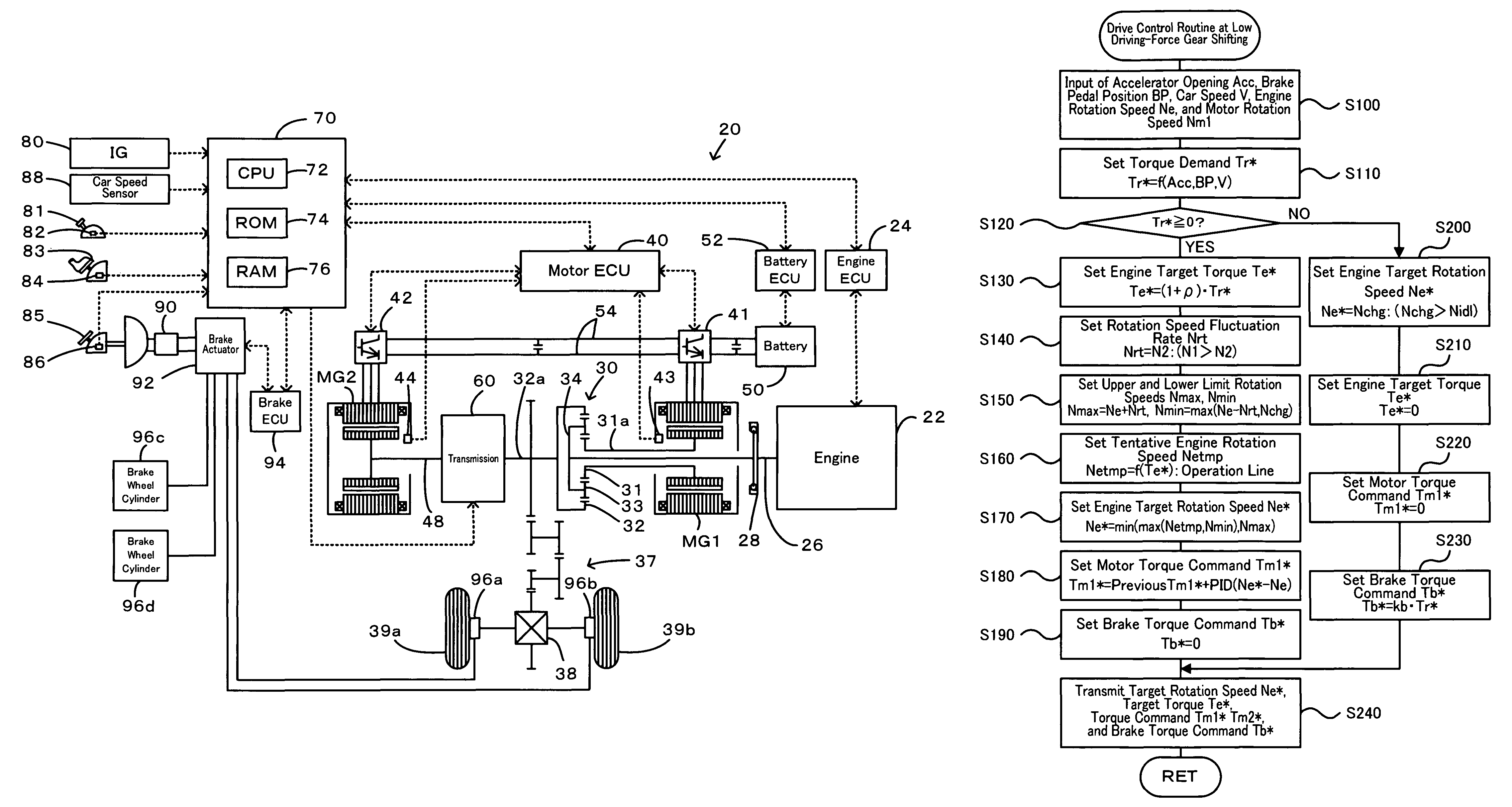
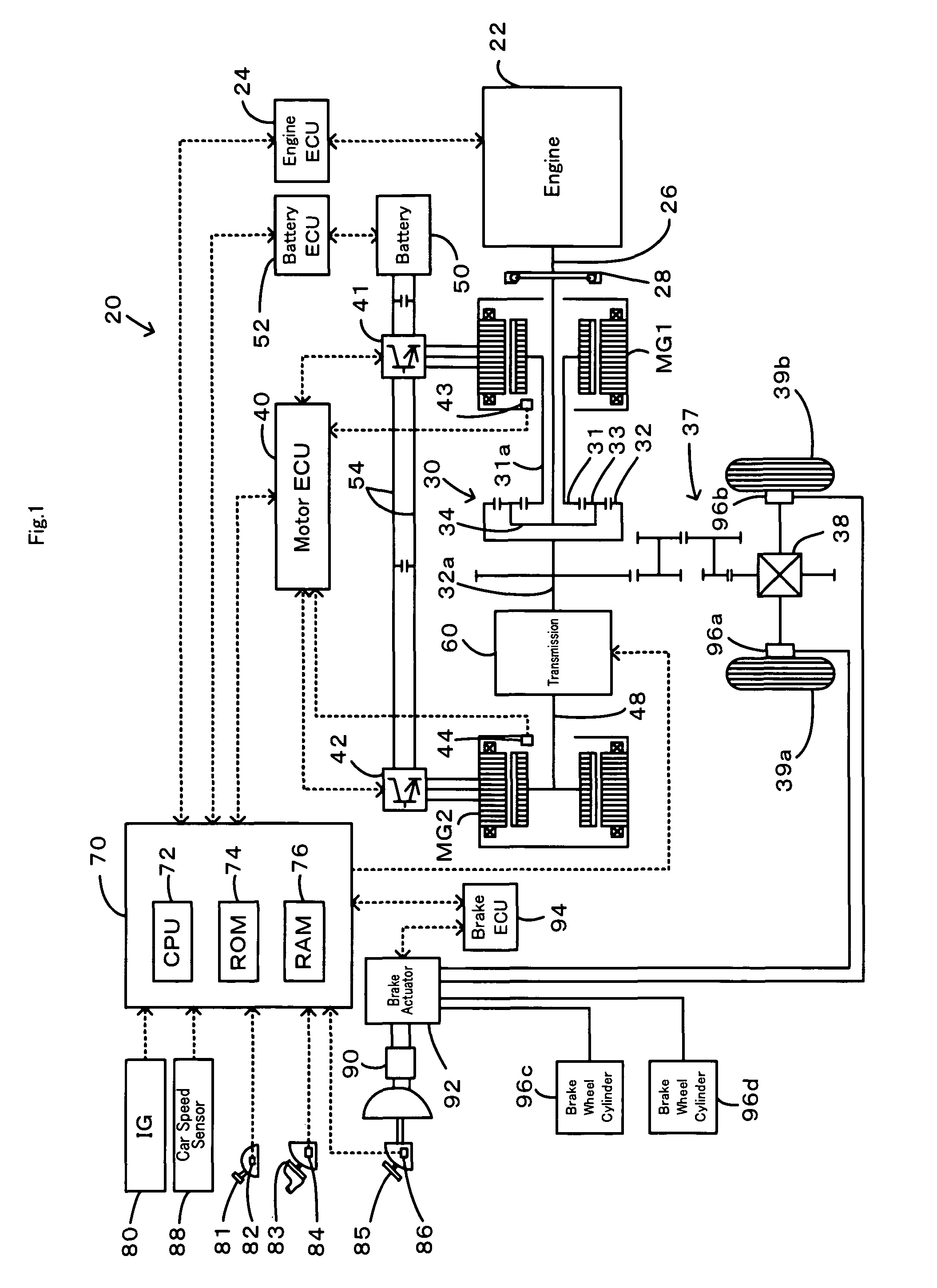
[0030]One mode of carrying out the invention is discussed below as a preferred embodiment with reference to the accompanied drawings. FIG. 1 schematically illustrates the configuration of a hybrid vehicle 20 in one embodiment of the invention. As illustrated, the hybrid vehicle 20 of the embodiment includes an engine 22, a three shaft-type power distribution and integration mechanism 30 that is linked to a crankshaft 26 or an output shaft of the engine 22 via a damper 28, a motor MG1 that is connected to the power distribution and integration mechanism 30 and has power generation capability, a motor MG2 that is linked to the power distribution and integration mechanism 30 via a transmission 60, a brake actuator 92 for controlling brakes in drive wheels 39a, 39b and driven wheels (not shown), and a hybrid electronic control unit 70 that controls the whole driving system of the hybrid vehicle 20.

[0031]The engine 22 is an internal combustion engine that uses a hydrocarbon fuel, such as...


PUM


Abstract

When a gear of a transmission for transmitting torque of a motor to a drive shaft is shifted while an accelerator is off or an accelerator pedal is slightly stepped on, an upper limit rotation speed is set using a fluctuation rate of a value smaller than a value when the gear is not shifted, a target rotation speed of an engine is set using this upper limit rotation speed, and control is carried out so that an engine is operated at the target rotation speed. By this arrangement, when the accelerator pedal is stepped on and a large torque demand is demanded, rise of the engine rotation speed is restricted, a portion used for raising the rotation speed in power outputted from the engine is made smaller, and a larger power can be outputted to the drive shaft.

Description

[0001]This is a 371 national phase application of PCT / JP2007 / 054014 filed 2 Mar. 2007, claiming priority to Japanese Patent Application No. JP 2006-063057 filed 8 Mar. 2006, the contents of which are incorporated herein by reference.TECHNICAL FIELD[0002]The present invention relates to a vehicle, a driving device and a control method thereof.BACKGROUND ART[0003]As this type of vehicle, a vehicle has been proposed, comprising an engine, a planetary gear mechanism in which a carrier is connected to a crankshaft of the engine and a ring gear is connected to an axle side, a first motor generator mounted to a sun gear of the planetary gear mechanism, and a second motor generator mounted to the axle side through a transmission (See Patent Document 1, for example). In this vehicle, power from the engine is torque-converted to running power by the planetary gear mechanism, the first motor generator and the second motor generator with gear shifting by the transmission with charge / discharge o...

Claims


Application Information

Patent Timeline
Patent Type & Authority Patents(United States)
IPC IPC(8): B60W10/06B60W10/10B60K6/445B60K6/448B60K6/52B60K6/547B60L50/16B60W10/04B60W10/08B60W10/11B60W10/113B60W10/115B60W20/00F02D29/00F02D29/02F16H59/14F16H59/42F16H59/48F16H61/04F16H61/68F16H61/684F16H61/686F16H61/688F16H63/40F16H63/50
CPCB60K6/445B60L11/14B60W10/06B60W10/08B60W10/10B60W20/00B60L11/123Y10T477/26B60L2220/14B60L2240/423B60L2240/486B60W2540/10B60W2710/0666B60W2710/083B60W2710/105F16H2061/6603Y02T10/56Y02T10/6217Y02T10/6286Y02T10/642Y02T10/7077Y02T10/6239Y10S903/93Y10S903/945B60L50/61B60L50/16Y02T10/40Y02T10/62Y02T10/64Y02T10/7072Y02T10/70B60W20/30
Inventor YAMANAKA, AKIHIROKAMICHI, KENSUKEGODA, HIDEAKIYAMAMOTO, MASAYATAJIMA, YOICHIAOKI, TAKESHIOKASAKA, KAZUOMI
Owner TOYOTA JIDOSHA KK
Why Eureka
Try Eureka