[0004]A vehicle, driving device and control method thereof of the present invention have an object to deal with a rapid change in a driving force required in the middle of gear shifting of a transmission with
rapidity. The vehicle, driving device and control method thereof of the present invention have another object to reduce a torque shock which can be generated at gear shifting of the transmission.
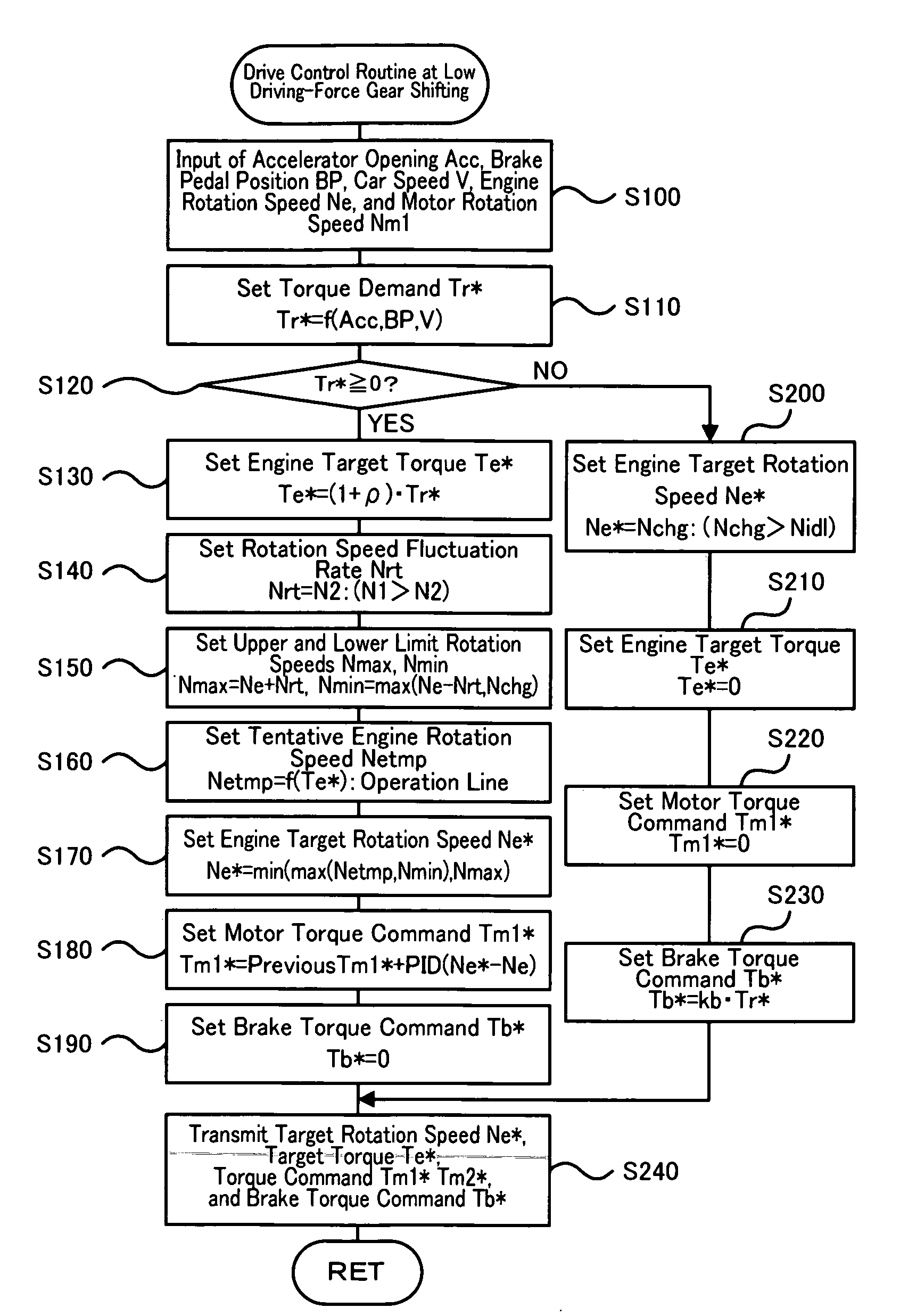
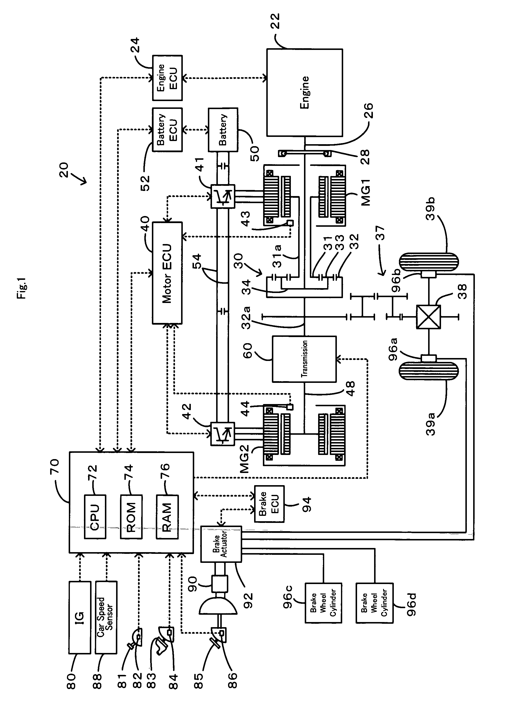
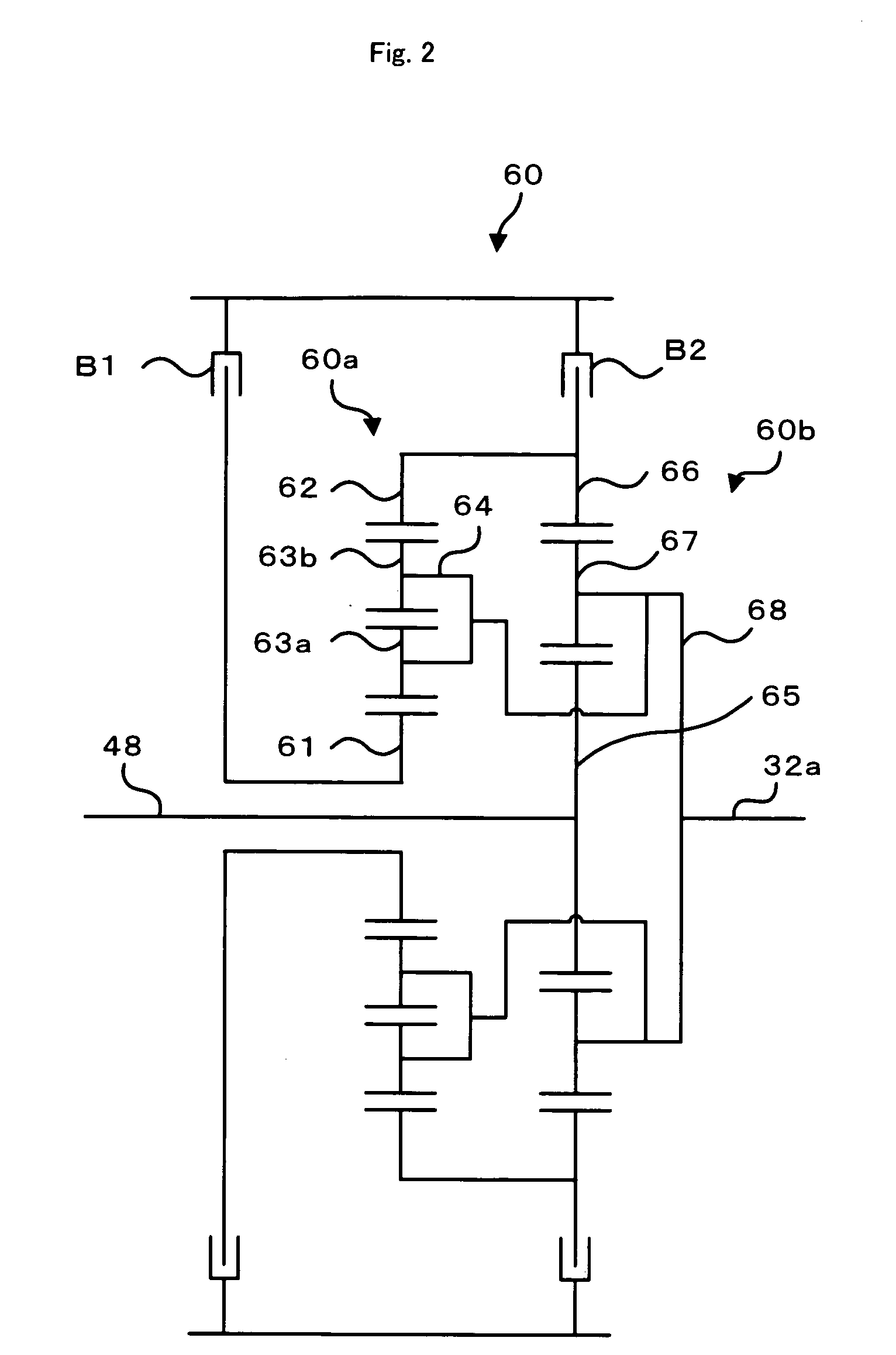
[0007]In the vehicle of the present invention, when the gear of the transmission mechanism is not shifted, the
internal combustion engine, the
electric power-mechanical power
input output mechanism and the motor are controlled so that running is made by the driving force based on the required driving force required for running with a change within the first change speed of the rotation speed of the
internal combustion engine, and when the gear of the transmission mechanism is shifted, the gear of the transmission mechanism is shifted with a change within the second change speed smaller than the first change speed of the rotation speed of the
internal combustion engine, and the internal
combustion engine, the
electric power-mechanical power
input output mechanism, the motor, and the transmission mechanism are controlled so that running is made by the driving force based on the required driving force required for running. That is, while the gear of the transmission mechanism is shifted, the change speed of the rotation speed of the internal
combustion engine is made smaller than that when the gear is not changed. By this arrangement, even if the required driving force is rapidly increased in the middle of the gear shifting of the transmission mechanism, energy used for raising the rotation speed of the internal
combustion engine can be reduced and power to be outputted to the first axle can be increased, by which a larger driving force can be obtained for running. As a result, the rapid change in the driving force required in the middle of the gear shifting of the transmission mechanism can be coped with quickly. Moreover, the torque shock which can be generated at gear shifting of the transmission mechanism can be reduced. Here, the first change speed and the second change speed may be made the maximum change speed at an increase of the rotation speed of the internal combustion engine.
[0011]In one preferable embodiment of the driving device of the present invention, when the gear of the transmission mechanism is not shifted, the internal combustion engine as well as the
electric power-mechanical power
input output mechanism and the motor are controlled so that running is made by the driving force based on the required driving force required for running with a change within the first change speed of the rotation speed of the internal combustion engine, and when the gear of the transmission mechanism is shifted, the gear of the transmission mechanism is shifted with a change within the second change speed smaller than the first change speed of the rotation speed of the internal combustion engine, and the internal combustion engine as well as the electric power-mechanical power input output mechanism, the motor, and the transmission mechanism are controlled so that running is made by the driving force based on the required driving force required for running. That is, while the gear of the transmission mechanism is shifted, the change speed of the rotation speed of the internal combustion engine is made smaller than that when the gear is not changed. By this arrangement, even if the required driving force is rapidly increased in the middle of the gear shifting of the transmission mechanism, energy used for raising the rotation speed of the internal combustion engine can be reduced and power to be outputted to the first axle can be increased, by which a larger driving force can be obtained for running. As a result, the rapid change in the driving force required in the middle of the gear shifting of the transmission mechanism can be coped with quickly. Moreover, the torque shock which can be generated at gear shifting of the transmission mechanism can be reduced.
[0013]In one preferable embodiment of the control method of the vehicle of the present invention, when the gear of the transmission mechanism is not shifted, the internal combustion engine, the electric power-mechanical power input output mechanism and the motor are controlled so that running is made by the driving force based on the required driving force required for running with a change within the first change speed of the rotation speed of the internal combustion engine, and when the gear of the transmission mechanism is shifted, the gear of the transmission mechanism is shifted with a change within the second change speed smaller than the first change speed of the rotation speed of the internal combustion engine, and the internal combustion engine, the electric power-mechanical power input output mechanism, the motor, and the transmission mechanism are controlled so that running is made by the driving force based on the required driving force required for running. That is, while the gear of the transmission mechanism is shifted, the change speed of the rotation speed of the internal combustion engine is made smaller than that when the gear is not changed. By this arrangement, even if the required driving force is rapidly increased in the middle of the gear shifting of the transmission mechanism, energy used for raising the rotation speed of the internal combustion engine can be reduced and power to be outputted to the first axle can be increased, by which a larger driving force can be obtained for running. As a result, the rapid change in the driving force required in the middle of the gear shifting of the transmission mechanism can be coped with quickly. Moreover, the torque shock which can be generated at gear shifting of the transmission mechanism can be reduced.
[0015]In one preferable embodiment of the control method of the driving device of the present invention, when the gear of the transmission mechanism is not shifted, the internal combustion engine as well as the electric power-mechanical power input output mechanism and the motor are controlled so that running is made by the driving force based on the required driving force required for running with a change within the first change speed of the rotation speed of the internal combustion engine, and when the gear of the transmission mechanism is shifted, the gear of the transmission mechanism is shifted with a change within the second change speed smaller than the first change speed of the rotation speed of the internal combustion engine, and the internal combustion engine as well as the electric power-mechanical power input output mechanism, the motor, and the transmission mechanism are controlled so that running is made by the driving force based on the required driving force required for running. That is, while the gear of the transmission mechanism is shifted, the change speed of the rotation speed of the internal combustion engine is made smaller than that when the gear is not changed. By this arrangement, even if the required driving force is rapidly increased in the middle of the gear shifting of the transmission mechanism, energy used for raising the rotation speed of the internal combustion engine can be reduced and power to be outputted to the first axle can be increased, by which a larger driving force can be obtained for running. As a result, the rapid change in the driving force required in the middle of the gear shifting of the transmission mechanism can be coped with quickly. Moreover, the torque shock which can be generated at gear shifting of the transmission mechanism can be reduced.


