In-wheel motor system

An in-wheel motor and motor technology, which are applied in the field of in-wheel motor systems, can solve the problems of inability to independently replace the electric motor 50a, the planetary reducer 50b, the problem of durability, and the large load torque of the power transmission mechanism, and achieve grounding performance. The effect of improving, improving durability, and improving ride comfort

Inactive Publication Date: 2009-02-18
BRIDGESTONE CORP
View PDF3 Cites 29 Cited by
  • Summary
  • Abstract
  • Description
  • Claims
  • Application Information

AI Technical Summary

Problems solved by technology

[0009] However, in the above-mentioned conventional in-wheel motor system, the wheels 56 and the planetary speed reducer 50b with a relatively large output torque are connected by the constant velocity joint 55 as the power transmission mechanism, so the load torque of the power transmission mechanism is relatively large. So there is a problem with persistence
[0010] In addition, the characteristics of the motor, the reduction ratio of the reduction gear mechanism, etc. need to be selected according to the size of the tire, the required torque, etc. The problem that the electric motor 50a or the planetary reducer 50b cannot be replaced independently

Method used


Image

  • In-wheel motor system
  • In-wheel motor system
  • In-wheel motor system

Examples


Embodiment approach 1

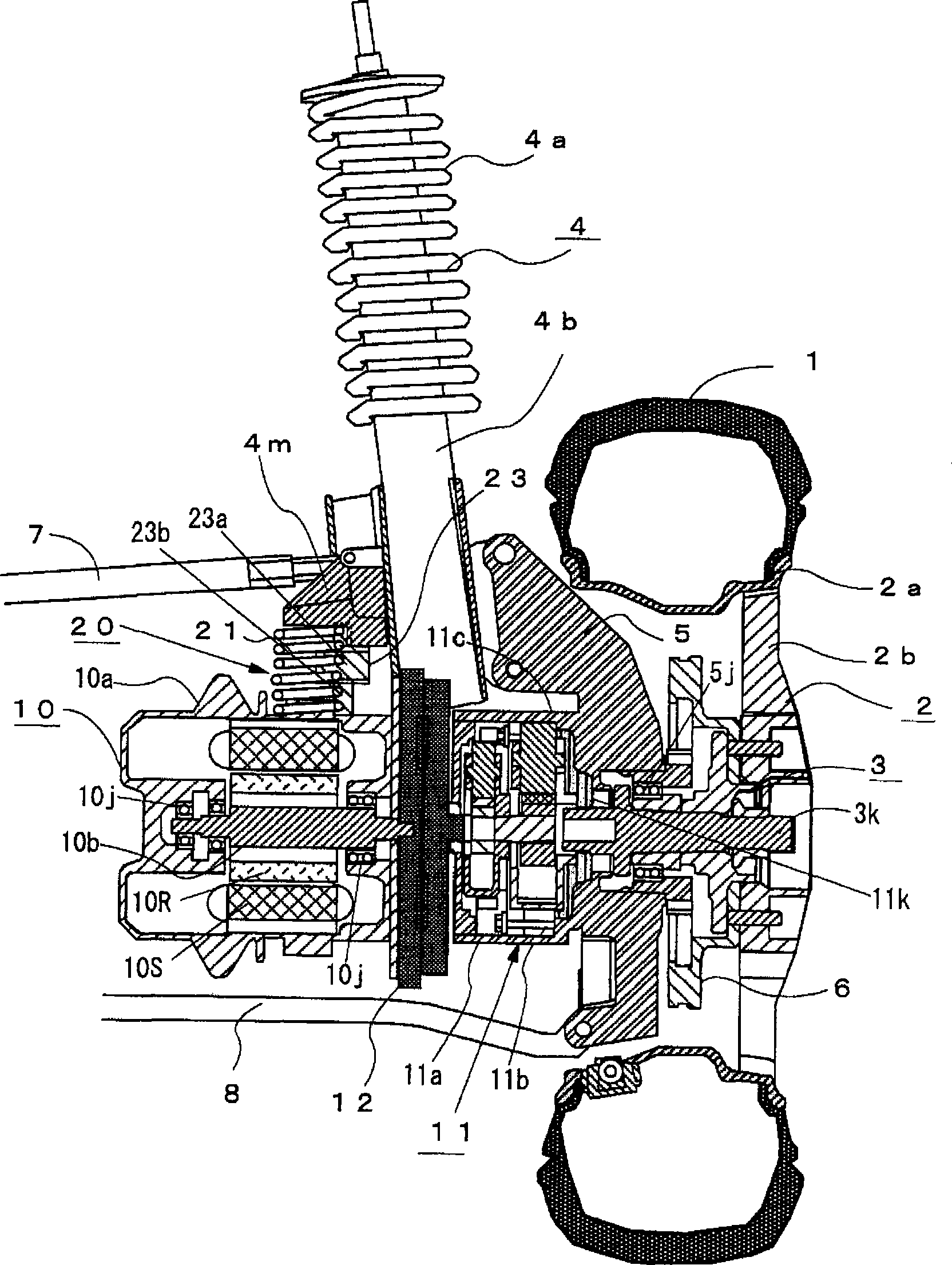
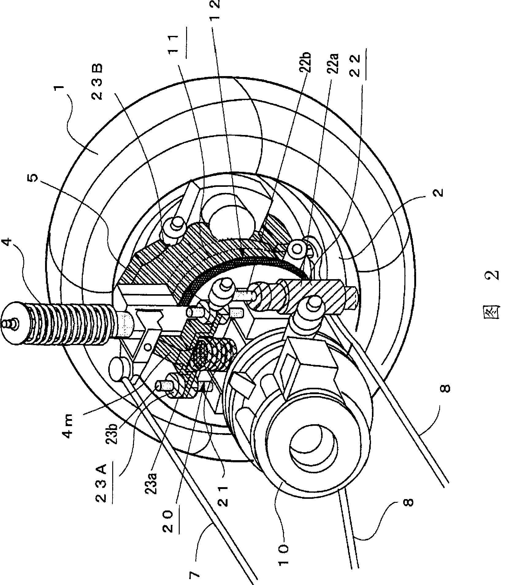
[0045] figure 1 It is a longitudinal sectional view showing the structure of the in-wheel motor system according to the first preferred embodiment of the present invention, and FIG. 2 is a perspective view. In each figure, reference numeral 1 is a tire, reference numeral 2 is a wheel composed of a rim 2a and a disc 2b, and reference numeral 3 is a hub connected to the above-mentioned wheel 2 at the rotation axis of the wheel 2, 4 is a strut having a coil spring 4a and a shock absorber 4b and suspending the steering knuckle 5 connected to the hub 3 via a bearing 5j on the vehicle body; 6 is a braking device installed on the hub 3; The upper arm 8 to which the strut 4 is connected is a lower arm that supports the knuckle 5 from below.

[0046] In addition, reference numeral 10 is an electric motor including a motor case 10a supporting a stator 10S, an output shaft 10b rotatably attached to the motor case 10a via a bearing 10j, and a rotor attached to the output shaft 10b. 10R...

Embodiment approach 2

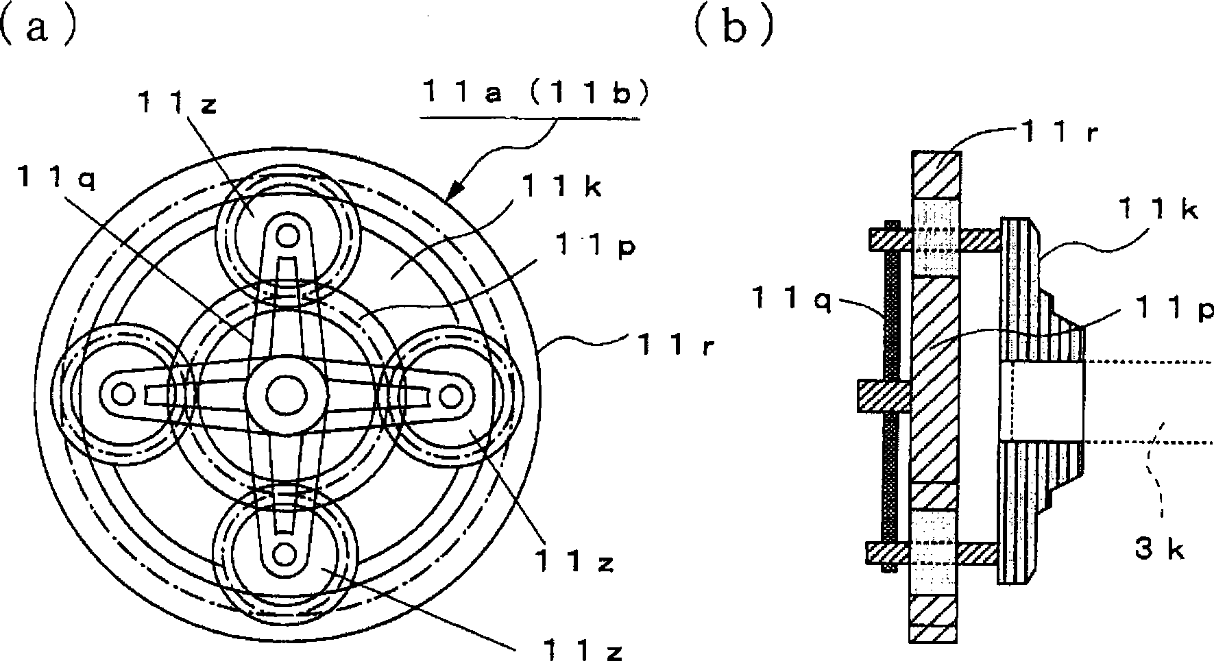
[0061] In the above-mentioned preferred embodiment 1, the electric motor 10 and the reduction gear mechanism 11 are packaged separately, and the motor mounting member 4m is provided on the lower side of the above-mentioned stay 4, and the stator 10S supporting the above-mentioned motor 10 is supported by the buffer mechanism 20. The motor housing 10a is mounted on the above-mentioned motor mounting member 4m, and the casing 11c of the above-mentioned reduction gear mechanism 11 is integrally formed with the steering knuckle 5, but as Figure 5 And as shown in FIG. 6 , the electric motor 10 and the reduction gear mechanism 11 can also be combined by using the flexible coupling 12, and the motor housing 10a supporting the stator 10S of the electric motor 10 is mounted on the motor mounting member 4m through the buffer mechanism 20. Above, the case 11c of the reduction gear mechanism 11 is fixed on the steering knuckle 5 .

[0062] Also in this case, the reduction gear mechanism ...


PUM


Abstract

An electric motor (10) and a speed reduction gear mechanism (11) are coupled by a flexible coupling (12) that is a power transmission mechanism such as an Oldham's coupling. A casing (11c) of the speed reduction gear mechanism (11) is formed integrally with a knuckle (5) as a component of vehicle's unsprung portion, or alternatively, is attached to the knuckle (5). Further, a motor case (10a) of the electric motor (10) is attached to a motor installation member (4m) via a shock absorbing mechanism (20), the motor installation member (4m) being provided on the lower side of a strut (4) for supporting the knuckle (5). The shock absorbing mechanism (20) has a spring member (21), a damper, and two guide members (23) for guiding the direction of operation of the spring member (21) and the damper. The construction allows the mass of the motor (10) to act as the mass of a dynamic damper. An in-wheel motor system thus obtained improves ground contact performance and ride quality of a vehicle traveling on a bad road and has good space efficiency.

Description

technical field [0001] The present invention relates to an in-wheel motor system having a drive motor for driving the wheel in a wheel, and more particularly to an in-wheel motor system having a structure in which the motor is supported on a running part of a vehicle via a buffer mechanism or a buffer member . Background technique [0002] Recently, an in-wheel motor system in which a drive motor such as a geared motor in which an electric motor is integrally assembled into a wheel is used in a vehicle driven by a motor such as an electric vehicle. In the motor housing, or the electric motor and the planetary reducer are integrally assembled into the motor housing. [0003] On the other hand, in a vehicle having a suspension mechanism such as a spring in the running part, generally, the greater the mass corresponding to the mass of non-suspended parts such as wheels, knuckles, and suspension arms, that is, the so-called unsprung mass, the tires will The more the ground for...

Claims


Application Information

Patent Timeline
Patent Type & Authority Applications(China)
IPC IPC(8): B60K7/00B60K17/14B60G3/18B60L15/00B60G13/16H02K7/116
CPCB60G2204/4304B60G13/18B60K17/30B60G7/008H02K7/14H02K7/006B60G2200/17B60G2204/148B60G3/20B60K2007/0053B60G2202/25B60G2204/129B60K2007/0092B60G2200/42Y02T10/641B60G2204/4191H02K7/116B60G2204/30B60G2200/156B60G15/04B60K17/02B60K17/046B60G2200/144B60K7/0007B60G2202/312B60G2204/182B60G2206/50B60L2220/44B60L2220/46Y02T10/64
Inventor 西冈聪岩野治雄田代胜巳
Owner BRIDGESTONE CORP
Why Eureka
Try Eureka