Control method for improving smoothening capability of excavator

A control method and excavator technology, which is applied in the direction of earth mover/excavator, construction, etc., can solve the difficulty of reasonably determining the size of the orifice, occupying the control main valve control pipeline, increasing the complexity of pipeline control, etc. problems, achieve the best leveling performance, reduce production and maintenance costs, and achieve good leveling effects

Inactive Publication Date: 2009-08-19
SANY HEAVY MACHINERY
View PDF0 Cites 14 Cited by
  • Summary
  • Abstract
  • Description
  • Claims
  • Application Information

AI Technical Summary

Problems solved by technology

However, because the size of the orifice is difficult to reasonably determine, the effect achieved by this method is not very great, and it also increases the complexity of the control of the pipeline, occupying the limited control pipeline of the control main valve

Method used


Image

  • Control method for improving smoothening capability of excavator
  • Control method for improving smoothening capability of excavator
  • Control method for improving smoothening capability of excavator

Examples


Embodiment 1

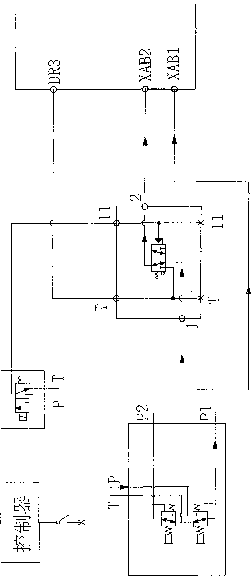
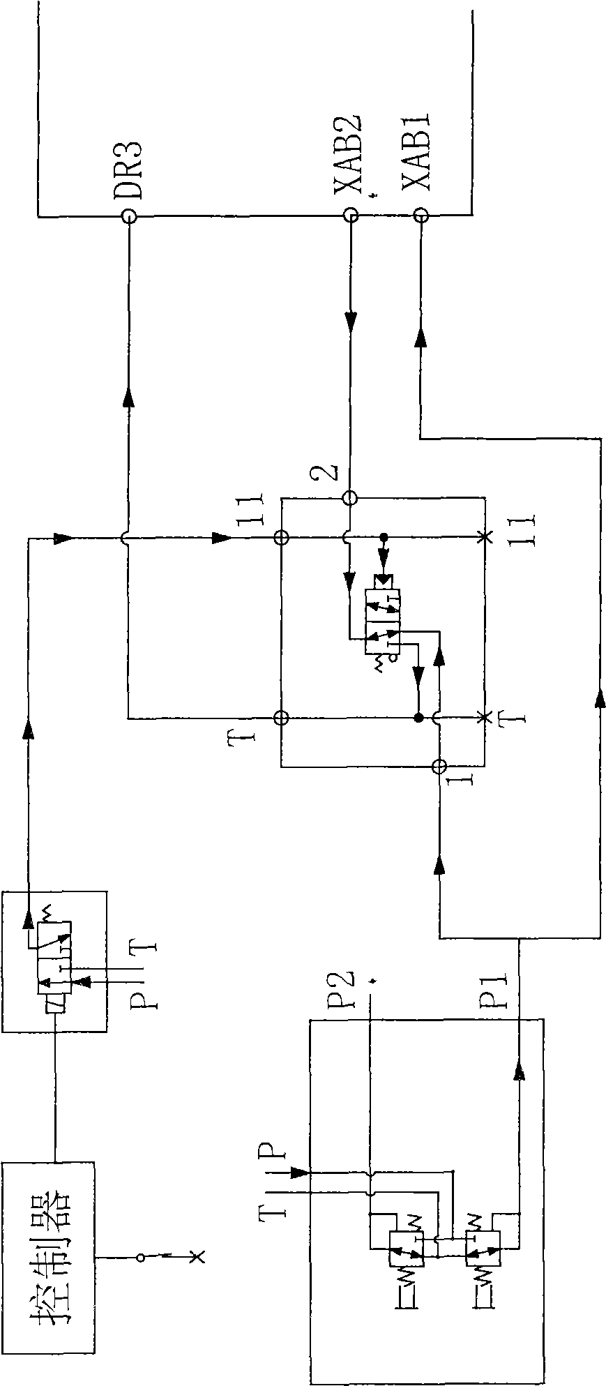
[0020] Example 1: see Figure 1 to Figure 2 As shown, a control method for improving the leveling performance of an excavator is provided with a hydraulic control directional valve on the boom confluence circuit in the hydraulic circuit of the excavator, and the control end 11 of the hydraulic control valve is connected to a solenoid valve, The control end of the solenoid valve is connected to the controller, such as figure 1 As shown, the input pin 1 of the hydraulic control directional valve is connected to the output pin P1 of the boom pilot valve in the confluence circuit, and its output pin 2 is connected to the boom confluence spool XAB2 pin in the confluence circuit, at the pilot valve output end The P1 pin is connected in parallel with an oil delivery line at the same time, which is connected to the XAB1 pin of the main valve core port of the boom, and the oil return end T of the hydraulic control directional valve is connected to the main valve oil return DR3 pin.

[002...

Embodiment 2

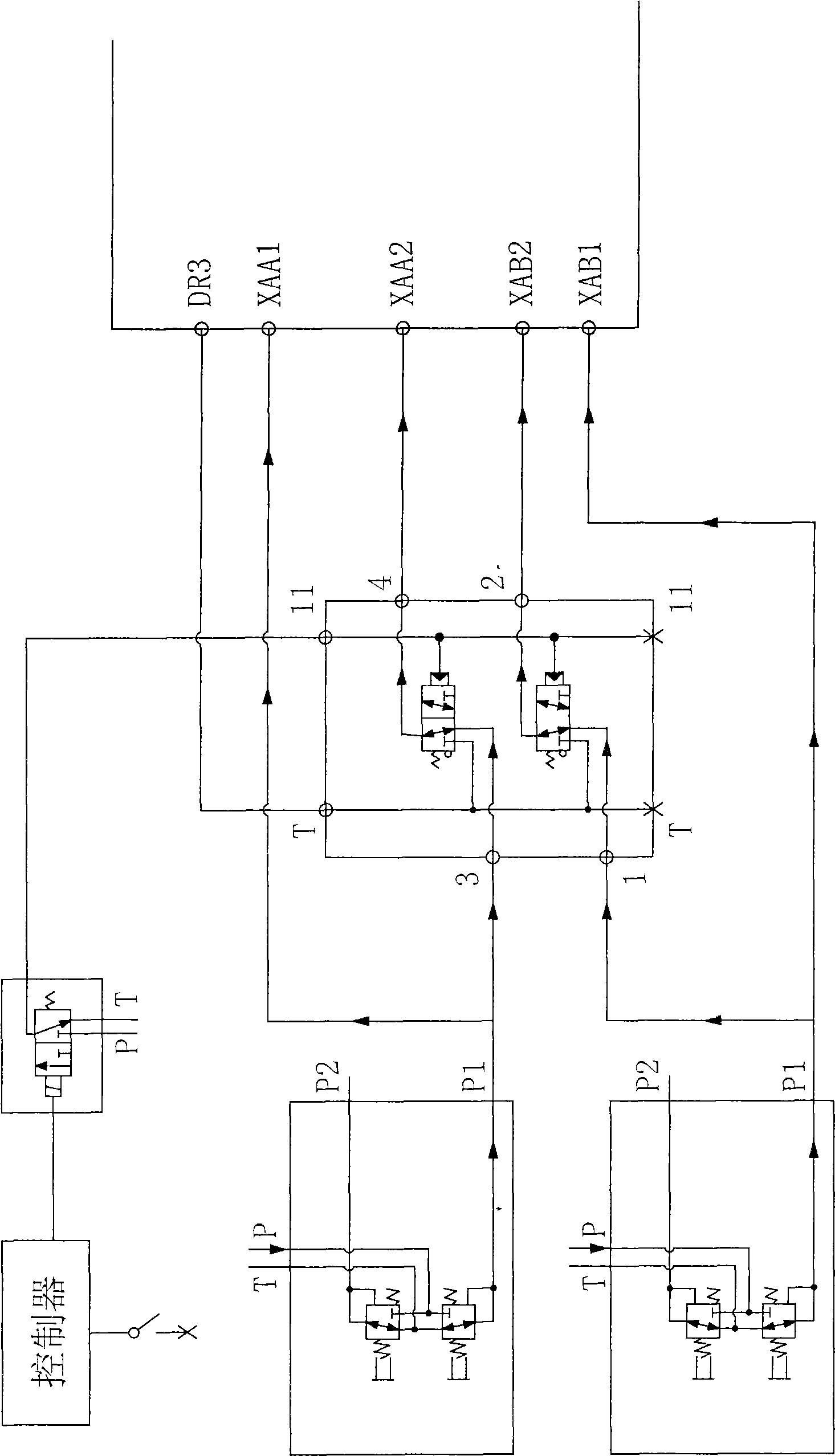
[0022] Example 2: see Figure 3 to Figure 4 As shown, a control method for improving the leveling performance of an excavator is provided with a hydraulic control directional valve on the boom confluence circuit and the stick excavation confluence circuit in the hydraulic circuit of the excavator. The control end of the hydraulic control valve is 11 feet Connected to a solenoid valve, the control end of the solenoid valve is connected to the controller, such as image 3 As shown, the hydraulic control directional valve is provided with a reversing valve connected in series with the boom confluence circuit and the stick excavation confluence circuit. The control end is connected in parallel to form the control end 11 feet, and the hydraulic control directional valve input end 1 foot and the confluence circuit The output of the middle boom pilot valve is connected to the P1 pin, the input 3 is connected to the stick digging pilot valve output P1 in the confluence loop, and the output...


PUM


Abstract

The invention discloses a control method for improving the flat ground property of an excavating machine, which is characterized by comprising the following steps: at least a confluent circuit of the excavating machine hydraulic circuits is provided with a liquid control directional valve, the control end of the liquid control directional valve is connected with an electromagnetic valve, and the control end of the electromagnetic valve is connected with a controller; the controller sends out electrifying signals to connect the electromagnetic valve after the flat ground mode is started, the electromagnetic valve controls the direction change of the liquid control directional valve, the confluent circuit is closed and oil is solely supplied by a main valve core oil port; the electromagnetic valve lose electricity after the flat ground mode is shut down, and the liquid control directional valve resets to connect the confluent circuit. By arranging the liquid control directional valve in the confluent circuit, and controlling the direction change through an electromagnetic valve to control the on-and-off of the corresponding confluent circuit, the method realizes controlling the system compound action flow by a simple hydraulic circuit and obtaining an optimal flat ground property and comfort level.

Description

Technical field [0001] The invention relates to an excavator operation control method, in particular to a control method for improving the leveling performance of the excavator. Background technique [0002] The working conditions of excavators are mainly as follows: 1. Flat excavation and loading; 2. Excavation and loading below the stop surface; 3. Digging; 4. Leveling the ground; 5. Slope repair; 6. Lifting. The leveling function is one of the important functions of the excavator. The leveling function is usually realized by the continuous and coordinated compound action of the hydraulic system controlling the boom, the stick and the bucket. The effect of the leveling performance of the excavator has a great relationship with the movement speed of the boom, stick and bucket during compound actions. Especially when carrying out the combined action of stick excavation and boom lifting, how to grasp the coordination of the action of the boom and the stick will determine the level...

Claims


Application Information

Patent Timeline
Patent Type & Authority Applications(China)
IPC IPC(8): E02F9/22
Inventor 戴晴华陈克雷权喜
Owner SANY HEAVY MACHINERY
Why Eureka
Try Eureka