Pneumatic tire

a technology of pneumatic tires and treads, applied in the field of pneumatic tires, can solve the problems of deteriorating grounding properties, reducing the contact area between tires and road surfaces, deteriorating rigidity of land portion of treads, etc., and achieves the effects of suppressing the leaning deformation of land portions, improving grounding properties of land portions, and improving braking and driving performan

Active Publication Date: 2015-01-15
BRIDGESTONE CORP
View PDF9 Cites 12 Cited by
  • Summary
  • Abstract
  • Description
  • Claims
  • Application Information

AI Technical Summary

Benefits of technology

[0043]According to the present invention, it is possible, in tires include a tread with land portions each having one or more sipes, to well improve braking and driving performance on both icy-snowy road and dry road. This is due to suppressing the leaning deformation of the land portion and improving the grounding property of the land portion while suppressing the lack of the sipe edge.

Problems solved by technology

The provision of more sipes in the tread surface may increase the edge components thereof, however on the other hand, it deteriorates the rigidity of the land portion of the tread.
In this case, the land portion is leaned and deformed by being loaded when the vehicle is braking, driving, or turning, and it caused a problem that the contact area of the tire and road surface is reduced and then the grounding property is deteriorated.
However, when it comes to applying the sipes described in the patent document 1 to the tire for all seasons, which may be used not only on icy-snowy road but also on dry road and having large frictional coefficient and input a large force to the tread surface, there are cases especially as getting input on dry road that the edge of sipes are get involved between the tread surface and end up to be lacked.

Method used


Image

  • Pneumatic tire
  • Pneumatic tire
  • Pneumatic tire

Examples


example 1

[0113]In order to confirm the effect of the present invention, experimentally manufactured the following tires; Invention Example tires (Invex) 1-1 through 1-5 according to the first aspect of the present invention, Convention Example tire (Convex) according to the conventional examples, and Comparative Example tires (Comex) 1-1 through 1-3, and evaluated each tires.

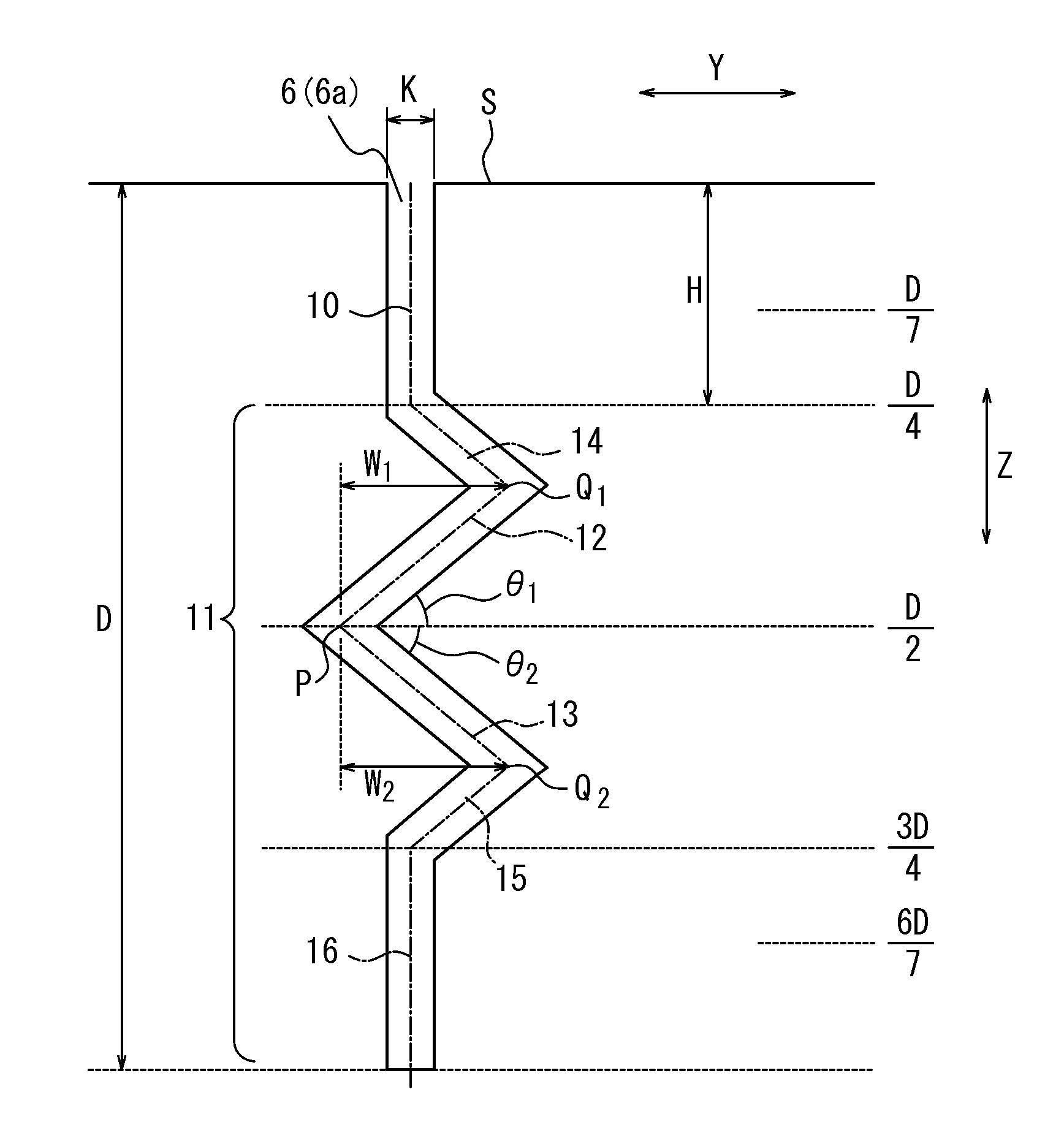
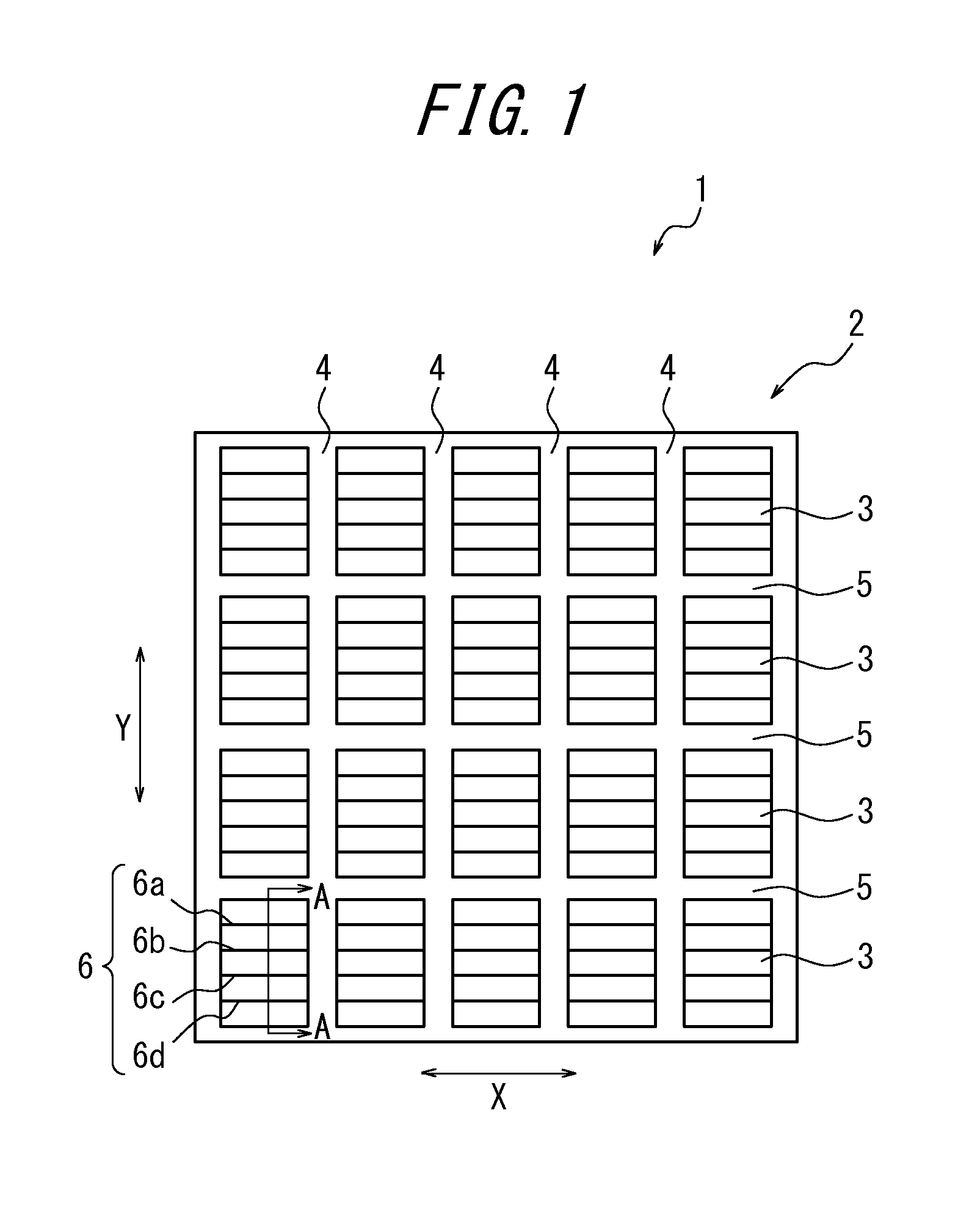
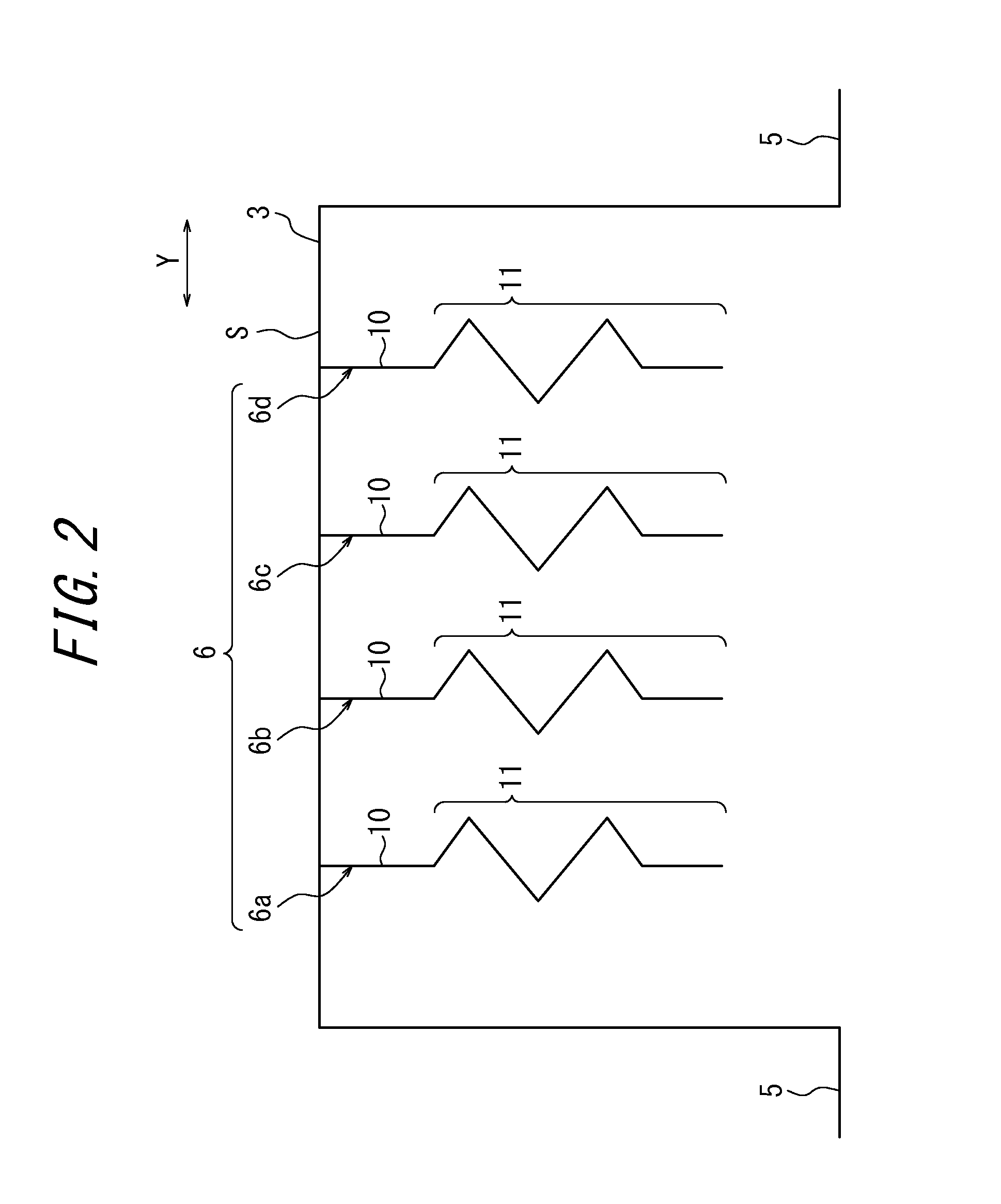
[0114]Invention tire 1-1 having tire size 205 / 55R16, a tread pattern described in FIG. 1, and each block-shaped land portion is provided with four sipes described in FIG. 2 and FIG. 3. The sipes are straightly extending toward the tire width direction on a road surface as described in FIG. 1. Each elements of tire is shown in Table 1-1.

[0115]Invention tires 1-2 through 1-5 is same as the invention tire 1-1 except that the each element of the sipes are varied as in Table 1.

[0116]Convention tire is same as the invention tire 1-1 except that the sipe shape in the cross-sectional view when taken along a plane which is perpen...

example 2

[0122]In order to confirm the effect of the present invention, experimentally manufactured the following tires; Invention Example tires (Invex) 2-1 through 2-15 according to the second aspect of the present invention, Convention Example tire (Convex) according to the conventional example, and Comparative Example tires (Comex) 2-1 through 2-9, and evaluated each tires.

[0123]The Invention Tire 2-1 having tire size 205 / 55R16, a tread pattern described in FIG. 1, and each block-shaped land portion is provided with four sipes described in FIG. 2 and FIG. 3. The sipes are straightly extending toward the tire width direction on a road surface as described in FIG. 1. Each elements of tire is shown in Table 1.

[0124]Invention tires 2-2 through 2-15 is same as the invention tire 2-1 except that the each element of the sipe are varied as in Tables 2-1 and 2-2.

[0125]Convention tire is same as the Invention Example tire 2-1 except that the sipe shape in the cross-sectional view when taken along a...

example 3

[0130]In order to confirm the effect of the tire comprising the sipes according to the second aspect of the present invention, wherein having plate-like regions at either side or both sides of the longitudinal direction of the sipe, manufactured the following tires; Invention Example tires (Invex) 3-1 through 3-25 according to the second aspect of the present invention, Convention Example tire (Convex) according to the conventional example, and Comparative Example tires (Comex) 3-1 through 3-12, and evaluated each tires.

[0131]The Invention Tire 3-1 having tire size 205 / 55R16, a tread pattern described in FIG. 1, and each block-shaped land portion is provided with four sipes described in FIG. 2 and FIG. 3. The sipes are straightly extending toward the tire width direction on a road surface as described in FIG. 1. Each elements of tire is shown in Table 3.

[0132]Invention tires 3-2 through 3-25 is same as the invention tire 3-1 except that the each element of the sipe are varied as in ...


PUM


Abstract

A pneumatic tire comprising one or more sipes having a depth (D) and, as seen in a widthwise section of the sipe, a perpendicular portion and a bend portion. The bend portion has, a first sub-bend point in a depth region of D/2-D/7, a main-bend point in a depth region of D/4-3D/4, and a second sub-bend point a depth region of D/2-6D/7, forming first and second inclined sections between the bend points. Each of the first and second inclined sections forms acute angles (θ1, θ2) of 30°≦θ1≦60° and 30°≦θ2≦60°, relative to a tangent of tread surface. The first inclined section has an area (a1) and the second inclined section has an area (a2), and ratios (a1/A and a2/A) of the area (a1) and (a2) to an orthographic projection area (A) of the sipe are not less than 0.1.

Description

TECHNICAL FIELD[0001]This invention relates to a pneumatic tire having a plurality of land portions in a tread, and one or more sipes are provided in the land portion.BACKGROUND ART[0002]Conventionally, it has been attempted to increase edge components of the tread surface by means of providing plural of sipes in the land portion of the tread surface so as to realize excellent driving performance on icy-snowy road.[0003]The provision of more sipes in the tread surface may increase the edge components thereof, however on the other hand, it deteriorates the rigidity of the land portion of the tread. In this case, the land portion is leaned and deformed by being loaded when the vehicle is braking, driving, or turning, and it caused a problem that the contact area of the tire and road surface is reduced and then the grounding property is deteriorated.[0004]Patent Document 1 discloses a pneumatic tire comprising sipes which extends in a zigzag manner, having a bend portion with plural of...

Claims


Application Information

Patent Timeline
Patent Type & Authority Applications(United States)
IPC IPC(8): B60C11/12
CPCB60C2011/1209B60C2011/129B60C11/1236B60C2011/1295B60C11/1218B60C11/11
Inventor YOSHIKAWA, TOSHIHIKO
Owner BRIDGESTONE CORP
Why Eureka
Try Eureka